At this step, we want to be sure that the data flow from the field to the top level is correctly configured. Some data like the IP address of the device in the field (Switch, PLC, etc) may need to be prepared by the Network Admin team. As network protocols at the field level are not the same as office level at this step we concentrate on the field bus network and the communication between the field bus, control level and supervisory level (e.g. SCADA).
The automation pyramid classifies the different IT layers of industrial automated production plants. Every layer or level has its own tasks and IT infrastructure within the production plants.
Level 0- Field Level/Sensor Actuator
This level has devices, actuators, and sensors that are found in the field or on the production floor.
Level 1-Control Level/PLC
PLC’s operate at this level. At this level, you control and manipulate the devices in the field level that actually do the physical work. They take in information from all of the sensors, switches, and other input/output devices.
Level 2- Supervisory Level/SCADA
This level is known as the supervisory level. Where the previous level utilizes PLCs, this level utilizes SCADA. SCADA is short for supervisory control and data acquisition.
Level 3-Planning level/MES
The fourth level of the automation pyramid is called the planning level. This level utilizes a computer management system known as MES or manufacturing execution system. MES monitors the entire manufacturing process in a plant or factory from the raw materials to the finished product.
Level 4 — Enterprise level(Business Planning and Logistics)/ERP
The top of the pyramid is what is called the management level. This level uses the company integrated management system which is known as the ERP or enterprise resource planning. This is where a company’s top management can see and control its operations. ERP is usually a suite of different computer applications that can see everything going on inside a company.

Field level is the button level in the Automation pyramid and uses Fieldbus for communication between devices. Fieldbus is a group of protocols that are used in the industrial arena. The Fieldbus protocols have been standardized as IEC61158.
There are several protocols in the field ControlNet (Allen Bradley family), Modbus RTU and Modbus TCP (Mostly Schneider Electric), Profibus and Profinet (Mostly Siemens), EtherCAT (Beckhoff), INTERBUS (Phoenix Contact), ASi(Actuator Sensor Interface), HART and many more.
Shop Level
At the Shop level, the common protocol is ethernet and is mostly provided by the Network Admin team. For more detail about networks at the IT level visit Network Basics.
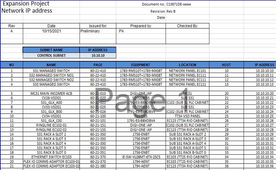
Network IP List
It includes IP address alongside equipment, location and drawing number of each device
.tg {border-collapse:collapse;border-spacing:0;} .tg td{border-color:black;border-style:solid;border-width:1px;font-family:Arial, sans-serif;font-size:14px; overflow:hidden;padding:10px 5px;word-break:normal;} .tg th{border-color:black;border-style:solid;border-width:1px;font-family:Arial, sans-serif;font-size:14px; font-weight:normal;overflow:hidden;padding:10px 5px;word-break:normal;} .tg .tg-z0iz{background-color:#fffc9e;text-align:left;vertical-align:top} .tg .tg-0lax{text-align:left;vertical-align:top}| NO | NAME | PAGE | EQUIPMENT | LOCATION | HOST | IP ADDRESS |
|---|---|---|---|---|---|---|
| 1 | S31 MANAGED SWITCH | 60-21-410 | 1783-RMS10T+1783-MX08T | NETWORK PANEL EC101 | 10 | 10.10.10.10 |
| 2 | S32 MANAGED SWITCH NO1 | 60-22-410 | 1783-RMS10T+1783-MX08T | NETWORK PANEL EC111 | 11 | 10.10.10.11 |
| 3 | S32 MANAGED SWITCH NO2 | 60-22-410 | 1783-RMS10T+1783-MX08T | NETWORK PANEL EC111 | 12 | 10.10.10.12 |
| 4 | S33 MANAGED SWITCH | 60-23-410 | 1783-RMS10T+1783-MX08T | NETWORK PANEL EC121 | 13 | 10.10.10.13 |
Network Fieldbus List
It includes Station Number, Master configuration such as baud rate and equipment, location and drawing number of each device
.tg {border-collapse:collapse;border-spacing:0;} .tg td{border-color:black;border-style:solid;border-width:1px;font-family:Arial, sans-serif;font-size:14px; overflow:hidden;padding:10px 5px;word-break:normal;} .tg th{border-color:black;border-style:solid;border-width:1px;font-family:Arial, sans-serif;font-size:14px; font-weight:normal;overflow:hidden;padding:10px 5px;word-break:normal;} .tg .tg-m9r4{background-color:#ffffc7;text-align:left;vertical-align:top} .tg .tg-0lax{text-align:left;vertical-align:top}| NO | NAME | PAGE | EQUIPMENT | LOCATION | Station Address | Comment |
|---|---|---|---|---|---|---|
| 1 | BTG.BDT.23 | 60-21-410 | 1783-3RK2200-0CT20-0AA3 | Field Distribution Module CP023 | 3 | Bus Loading File: ES1202336 |
Each Fieldbus has its own character and needs its own documents. For example, Bus loading calculation is required for ASi bus.
