These documents include information on the type of the cable, cable length and detail alongside gable name, drawing name, Source and destination (from-to) and electrical drawing number. In some documents, the cable gland is required to be specified in this document.
Equipment list (Step2) IO List (Step3) Network List (Step4) provide all the required component
| CABLE NAME | CABLE FROM | CABLE TO | DESCRIPTION | Drawing Page Ref for Connection.Page/Grid | Length (m) / Quantity | 2.5mm² 3 Core + E + N (Power Bus) | 2.5mm² 3 Core + E (Motor Cable) | 2.5mm² 2 Core + E (24VDC supply) | 1.5mm² 4 Core (E/Stop + Control) Grey control, Numbered cores | 1.5mm² 16 Core + E Grey control, Numbered cores | 3C & E (2.5mm) with Plug Fitted Unscreened, 3m (DMS Power) | 3C+SC & E (2.5mm) with Plug Fitted Screened, 3m (DMS to Motor) | V1-G-5M-PUR 5m 4 Core M12 to free end for PEs | V31-GM-5M-PUR 5m 4 Core M8 to free end for PEs | VAZ-2T1-FK-5M-PUR-V1-W ASi network splitter cable | Profibus Cable (Purple) | ASi Cable (Yellow) | ASi Cable AUX (Black) |
|---|---|---|---|---|---|---|---|---|---|---|---|---|---|---|---|---|---|---|
| -W_BTM003/BLG.BDT.23 | BTM003 | BLG.BDT.23 | MCP TO Collector Belt | -550/13 | 43 | X | ||||||||||||
| -W_BTM003/BlG.BDT.23n | BTM003 | BlG.BDT.23n | MCP TO Collector Belt | -551/13 | 33 | X | ||||||||||||
| -W_BTM003/BUS_3 | BTM003 | BUS_3 | MCP bus to BTG.BDT.24 | -053/32 | 28 | X | ||||||||||||
| -W_BTM003/BUS_2 | BTM003 | BUS_2 | MCP bus to BTG.BDT.302B | -053/22 | 35 | X | ||||||||||||
| -W_BTM003/BT1.29A.RMCP – P | BTM003 | BT1.29A.RMCP – P | MCP TO RMCP | -053/07 | 35 | X | ||||||||||||
| -W_BTM003/BT1.29B.RMCP – P | BTM003 | BT1.29B.RMCP – P | MCP TO RMCP | -053/07 | 35 | X | ||||||||||||
| -W_BTM003/ICM ABD 1&2 – P | BTM003 | ICM ABD 1&2 – P | MCP TO ABD (Power) | -053/42 | 35 | X |
Cable selection guide:
To calculate the Cable Sizing one needs to know the load parameter. The load parameters are:
Voltage (V): Specify the voltage
Phase arrangement: 1 Phase AC, 3 Phase AC or DC.
Load (kW, kVA, A, hp): Specify the load in kW, kVA, A, or hp. At the end of the day we use Amps as the main parameter but quite easy to convert from power to Amps as long as we know the voltage and Power factor.
PF: Specify the load power factor (cos&Phi) when the load is specified in kW or hp.
Max. volt drop (%): The maximum allowable voltage drop at the load. mentioned in the equipment documents.
Distance (m): The cable length in meters from the source to the load. The return length is automatically included by the calculator.
Cable type: The number of cores in the cable. Ignore the earth conductor in three-phase cables.
Insulation type: The type of insulation. Typically “Thermoplastic (PVC), 75°C” or “Thermoset (XLPE), 90°C”. In special cases “Thermoset (XLPE), 110°C” is used. Note that there is no option for “Thermoplastic (PVC), 90°C” (V-90) cables in AS/NZS 3008. In this case, you can use “Thermoset (XLPE), 90°C” in the calculator. However, bear in mind that V-90 cables cannot be exposed to high mechanical stress at 90°C. Refer to AS 3008 for more details.
Live core type: Copper, Flexible copper or Aluminium.
Live core size: Mostly we are seeking for smallest cable that meets the three criteria for current rating, voltage drop, and fault current rating.
Earth core type: Only copper is currently supported.
Earth core size: selecting Minimum Copper Earthing Conductor Size is preferable, although mostly the standard cable cover this part automatically.
The number of parallel cables (multi-core) or Active cables per phase (single-core): parallel cables is a series of cable that carries the shared load.
Typically only one cable per phase, for single- or multi-core cables. More than one cable may be selected for high load scenarios.
Cable installation: How the cable will be installed. Consider the worse case section of the cable installation. It applies a cofactor to the calculation.

An online calculator
https://www.jcalc.net/cable-sizing-calculator-as3008
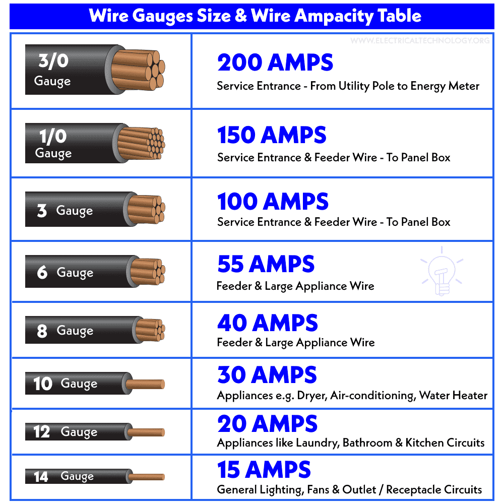
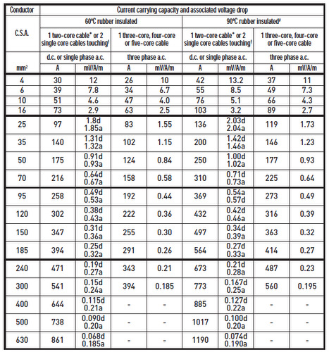
Guideline of wire current carrying capacity
In careful engineering the voltage drop, insulation temperature limit, thickness, thermal conductivity, and air convection and temperature should all be taken into account.
| AWG gauge | Diameter Inches | Diameter mm | Ohms per 1000 ft | Ohms per km | Max amps chassis wiring | Max amps power transmission |
| OOOO | 0.46 | 11.684 | 0.049 | 0.16072 | 380 | 302 |
| OOO | 0.4096 | 10.40384 | 0.0618 | 0.202704 | 328 | 239 |
| OO | 0.3648 | 9.26592 | 0.0779 | 0.255512 | 283 | 190 |
| 0 | 0.3249 | 8.25246 | 0.0983 | 0.322424 | 245 | 150 |
| 1 | 0.2893 | 7.34822 | 0.1239 | 0.406392 | 211 | 119 |
| 2 | 0.2576 | 6.54304 | 0.1563 | 0.512664 | 181 | 94 |
| 3 | 0.2294 | 5.82676 | 0.197 | 0.64616 | 158 | 75 |
| 4 | 0.2043 | 5.18922 | 0.2485 | 0.81508 | 135 | 60 |
| 5 | 0.1819 | 4.62026 | 0.3133 | 1.027624 | 118 | 47 |
| 6 | 0.162 | 4.1148 | 0.3951 | 1.295928 | 101 | 37 |
| 7 | 0.1443 | 3.66522 | 0.4982 | 1.634096 | 89 | 30 |
| 8 | 0.1285 | 3.2639 | 0.6282 | 2.060496 | 73 | 24 |
| 9 | 0.1144 | 2.90576 | 0.7921 | 2.598088 | 64 | 19 |
| 10 | 0.1019 | 2.58826 | 0.9989 | 3.276392 | 55 | 15 |
| 11 | 0.0907 | 2.30378 | 1.26 | 4.1328 | 47 | 12 |
| 12 | 0.0808 | 2.05232 | 1.588 | 5.20864 | 41 | 9.3 |
| 13 | 0.072 | 1.8288 | 2.003 | 6.56984 | 35 | 7.4 |
| 14 | 0.0641 | 1.62814 | 2.525 | 8.282 | 32 | 5.9 |
| 15 | 0.0571 | 1.45034 | 3.184 | 10.44352 | 28 | 4.7 |
| 16 | 0.0508 | 1.29032 | 4.016 | 13.17248 | 22 | 3.7 |
| 17 | 0.0453 | 1.15062 | 5.064 | 16.60992 | 19 | 2.9 |
| 18 | 0.0403 | 1.02362 | 6.385 | 20.9428 | 16 | 2.3 |
| 19 | 0.0359 | 0.91186 | 8.051 | 26.40728 | 14 | 1.8 |
| 20 | 0.032 | 0.8128 | 10.15 | 33.292 | 11 | 1.5 |
| 21 | 0.0285 | 0.7239 | 12.8 | 41.984 | 9 | 1.2 |
| 22 | 0.0254 | 0.64516 | 16.14 | 52.9392 | 7 | 0.92 |
| 23 | 0.0226 | 0.57404 | 20.36 | 66.7808 | 4.7 | 0.729 |
| 24 | 0.0201 | 0.51054 | 25.67 | 84.1976 | 3.5 | 0.577 |
| 25 | 0.0179 | 0.45466 | 32.37 | 106.1736 | 2.7 | 0.457 |
| 26 | 0.0159 | 0.40386 | 40.81 | 133.8568 | 2.2 | 0.361 |
| 27 | 0.0142 | 0.36068 | 51.47 | 168.8216 | 1.7 | 0.288 |
| 28 | 0.0126 | 0.32004 | 64.9 | 212.872 | 1.4 | 0.226 |
| 29 | 0.0113 | 0.28702 | 81.83 | 268.4024 | 1.2 | 0.182 |
| 30 | 0.01 | 0.254 | 103.2 | 338.496 | 0.86 | 0.142 |
| 31 | 0.0089 | 0.22606 | 130.1 | 426.728 | 0.7 | 0.113 |
| 32 | 0.008 | 0.2032 | 164.1 | 538.248 | 0.53 | 0.091 |
| Metric 2.0 | 0.00787 | 0.200 | 169.39 | 555.61 | 0.51 | 0.088 |
| 33 | 0.0071 | 0.18034 | 206.9 | 678.632 | 0.43 | 0.072 |
| Metric 1.8 | 0.00709 | 0.180 | 207.5 | 680.55 | 0.43 | 0.072 |
| 34 | 0.0063 | 0.16002 | 260.9 | 855.752 | 0.33 | 0.056 |
| Metric 1.6 | 0.0063 | 0.16002 | 260.9 | 855.752 | 0.33 | 0.056 |
| 35 | 0.0056 | 0.14224 | 329 | 1079.12 | 0.27 | 0.044 |
| Metric 1.4 | .00551 | .140 | 339 | 1114 | 0.26 | 0.043 |
| 36 | 0.005 | 0.127 | 414.8 | 1360 | 0.21 | 0.035 |
| Metric 1.25 | .00492 | 0.125 | 428.2 | 1404 | 0.20 | 0.034 |
| 37 | 0.0045 | 0.1143 | 523.1 | 1715 | 0.17 | 0.0289 |
| Metric 1.12 | .00441 | 0.112 | 533.8 | 1750 | 0.163 | 0.0277 |
| 38 | 0.004 | 0.1016 | 659.6 | 2163 | 0.13 | 0.0228 |
| Metric 1 | .00394 | 0.1000 | 670.2 | 2198 | 0.126 | 0.0225 |
| 39 | 0.0035 | 0.0889 | 831.8 | 2728 | 0.11 | 0.0175 |
| 40 | 0.0031 | 0.07874 | 1049 | 3440 | 0.09 | 0.0137 |
Wiring Color Codes
Wiring for AC and DC power distribution branch circuits are colour coded for the identification of individual wires. In some jurisdictions, all wire colours are specified in legal documents. In other jurisdictions, only a few conductor colours are so codified. In that case, local custom dictates the “optional” wire colours.
IEC, AC: Most of Europe abides by IEC (International Electrotechnical Commission) wiring colour codes for AC branch circuits. These are listed in the table below. The older colour codes in the table reflect the previous style which did not account for proper phase rotation. The protective ground wire (listed as green-yellow) is green with a yellow stripe.

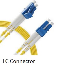
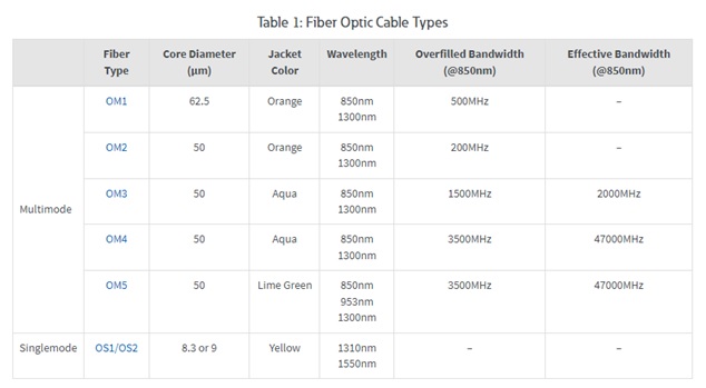
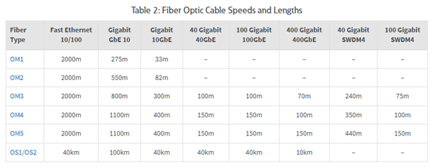
Fiber Optic
Single-mode fibres are designed to carry one mode of light over long distances. They have a small core typically 9 microns that carries one ray of light at a time. This allows them to carry large amounts of data over very long distances up to 10 km.
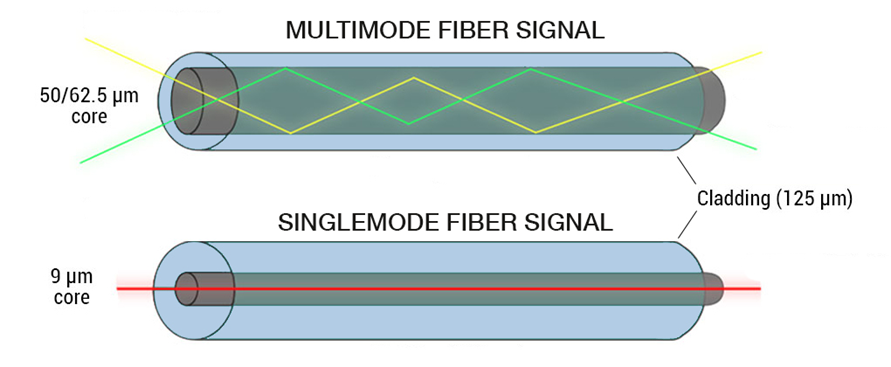
Multi-mode (Cheaper Option) fibres are designed to carry multiple modes of light over short distances. They have a large core typically 50 or 62.5 microns that carries multiple rays of light at the same time. This allows them to carry large amounts of data over shorter distances up to 2 km.
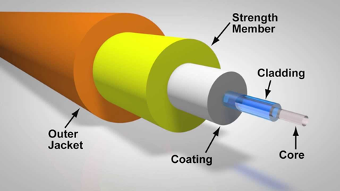
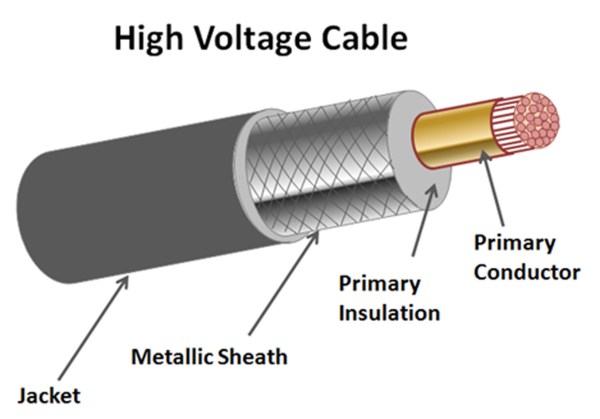
Cable Parts
Cable or Wire?
What is the difference between a wire and cable? This is one of the most basic questions that still need to be answered. Wire is a single conductor and cable is a group of two or more insulated conductors. If there was not any insulation on the two conductors then it would not be a cable, it would still be a single conductor which would classify as a wire.
Ingredients!
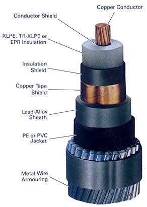
The picture above shows structure of a sample wire, although all cables or wire may don’t have all part of mentioned parts.
Insulation: two kind of insulation are common in industries
- PVC: Max. degree is 70 Celsius
- XLPE: Max. degree is 90 Celsius
If cable uses in outdoor circumstance the cable has Amour,
If cable uses in oily circumstance the cable has jacket
If cable uses for transferring DC or HV the cable has copper shield
The picture above shows a complete cable and most of cables don’t have all parts shown in the picture.
The conductor can be a single solid wire or made up of a number of thin strands. Solid or single-stranded wire is not very flexible and is used where rigid connections are acceptable or preferred – usually in high current applications in power switching contractors.
Stranded wire is flexible and most interconnections between components are made with it.
Wire specifications
There are several ways to describe the wire type. The most used method is to specify the number of strands in the conductor, the diameter of the strands, the cross sectional area of the conductor then the insulation type.
Example: 35/0.25 PVC 0.28 mm2 è the conductor comprises 35 strands. Each strand is 0.25mm and insulated with PVC the conductor has a cross-sectional area nominally of 0.28mm2.
Solid wire can also be specified using the Standard Wire Gauge or SWG system.
British Standard Wire Gauge is a set of wire sizes is generally abbreviated to SWG. It is also known as: Imperial Wire Gauge or British Standard Gauge.
D(AWG)=.005·92((36-AWG)/39) inch.
Note that in AWG the diameter goes up as the gauge goes down, but for metric gauges it is the opposite. Probably because of this confusion, most of the time metric sized wire is specified in millimeters rather than metric gauges.
The SWG number is equivalent to a specific diameter of conductor
| SWG | in | mm |
| 7/0 | 0.5 | 12.700 |
| 6/0 | 0.464 | 11.786 |
| 5/0 | 0.432 | 10.973 |
| 4/0 | 0.4 | 10.160 |
| 3/0 | 0.372 | 9.449 |
| 2/0 | 0.348 | 8.839 |
| 0 | 0.324 | 8.230 |
| 1 | 0.3 | 7.620 |
| 2 | 0.276 | 7.010 |
| 3 | 0.252 | 6.401 |
| 6 | 0.192 | 4.877 |
| 7 | 0.176 | 4.470 |
| 8 | 0.16 | 4.064 |
| 9 | 0.144 | 3.658 |
| 10 | 0.128 | 3.251 |
| 11 | 0.116 | 2.946 |
| 12 | 0.104 | 2.642 |
| 13 | 0.092 | 2.337 |
| 14 | 0.08 | 2.032 |
| 15 | 0.072 | 1.829 |
| 16 | 0.064 | 1.626 |
| 17 | 0.056 | 1.422 |
| 18 | 0.048 | 1.219 |
| 19 | 0.04 | 1.016 |
| 20 | 0.036 | 0.914 |
| 21 | 0.032 | 0.813 |
| 22 | 0.028 | 0.711 |
| 23 | 0.024 | 0.610 |
| 24 | 0.022 | 0.559 |
| 25 | 0.02 | 0.5080 |
| 26 | 0.018 | 0.4572 |
| 27 | 0.0164 | 0.4166 |
| 28 | 0.0148 | 0.3759 |
| 29 | 0.0136 | 0.3454 |
| 30 | 0.0124 | 0.3150 |
| 31 | 0.0116 | 0.2946 |
| 32 | 0.0108 | 0.2743 |
| 33 | 0.01 | 0.2540 |
| 34 | 0.0092 | 0.2337 |
| 35 | 0.0084 | 0.2134 |
| 36 | 0.0076 | 0.1930 |
| 37 | 0.0068 | 0.1727 |
| 38 | 0.006 | 0.1524 |
| 39 | 0.0052 | 0.1321 |
| 40 | 0.0048 | 0.1219 |
| 41 | 0.0044 | 0.1118 |
| 42 | 0.004 | 0.1016 |
| 43 | 0.0036 | 0.0914 |
| 44 | 0.0032 | 0.0813 |
| 45 | 0.0028 | 0.0711 |
| 46 | 0.0024 | 0.0610 |
| 47 | 0.002 | 0.0508 |
| 48 | 0.0016 | 0.0406 |
| 49 | 0.0012 | 0.0305 |
| 50 | 0.001 | 0.0254 |
Wires in the market
Standards wires produce in different companies. But all companies produce below sizes:
Diameter mm2: 0.5 – 0.75 – 1 – 1.5 – 2.5 – 4-6-10-16-25-35-50-70-95-120-150-185-240-300-400-500
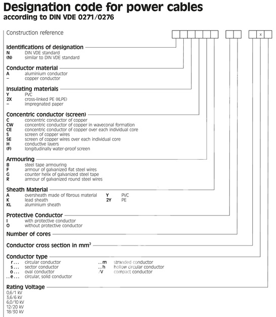
Power Cable specifications
Low Voltage: Cables generally used for rated voltage less than 1 kV.
Medium Voltage: Cables generally used for rated voltage between1 kV and 36 kV.
High Voltage: Cables generally used for rated voltage bigger than 36 kV.
Common type for describing a cable is NxM+M0. M shows Number of main wire inside of cable, N shows diameter of main wires, M0 shows one more wire in the cable uses for Earth.
For example: 3*25+15 means the cable has 3 main wires, diameters of wires are 25mm2 and it has one 15mm2 wire for earth.
Examples:
NA2XS2Y 1×35 RM/16 6/10 KV
Single core XPLPE insulated cable with PE sheath, circular, stranded aluminum conductor with nominal cross section 35mm2 cover with cooper screen 16 mm2 and rating voltage (U0/U) 6/10 KV
U0 is cable nominal voltage between contactor and metal covering or earth
U is cable nominal voltage between phase contactors for 3 phase u=√3 u0
