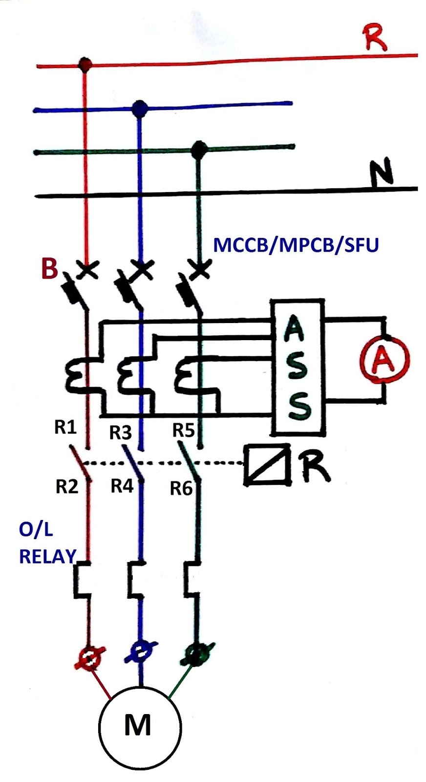
Protection Offered by DOL Starter:
The Motor starters not only provide a safe starting current but also provide protection to keep the motor safe during operation. It is clear that the DOL starter provides the full line voltage but it does provide the following protection:
Overcurrent Protection:
The condition that causes the flow of a faulty current in a large amount mostly due to a short circuit or ground fault is called overcurrent. The overcurrent condition can cause damage to the motor, power lines and can be a hazard for operators. Such an amount of current is too dangerous for a brief moment. In the DOL starter, we use a circuit breaker or fuses for protection against overcurrent. They open the circuit and breaks the current flow in an instant until the problem in the system is resolved. The fuse or circuit breaker is carefully selected with its rating kept in mind. Because we do not want the fuse to break but to tolerate the starting current as well as the heavy load current. The overcurrent breaker’s rating is kept a bit higher than the rated starting current of the motor.
Overload Protection:
The condition where the load connected to the motor increases beyond its limit and the motor draws an excessive amount of current is called overload condition. During overload, the current flow is beyond the safe limits which damage the wires as well as the motor windings. It melts the windings and may cause fire hazards.
In order to protect the motor from overloading, we use an overload relay that trips the power supply and protects the system from overheating. The overload relay monitors the current and breaks the current flow when it exceeds a certain limit for a period of time. The tripping mechanism may vary and depends on the application of the motor.
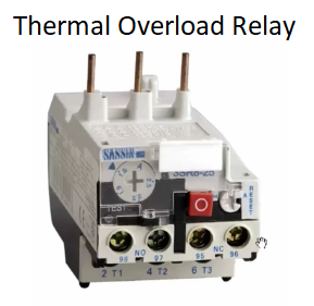
Thermal Overload Relay: This type of overload relay works on the principle of expansion due to the heat generated by the current flow. A bimetallic strip is used with different thermal expansion to break or make the circuit based on the temperature. bimetal thermal overload relay is a common thermal O.L relay
Magnetic overload relay: such relays works on the principle of the magnetic field generated by the current flow through a coil. An excessive current drawn by the motor (that is a predetermined amount) generates enough magnetic field to trips the contact terminals and breaks the current supply.
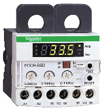
Electronic Overload Relay: Electronic relay is a solid-state device without any movable parts or contacts. It utilizes current sensors to monitor the motor current and has an adjustable setting that allows the tripping at a wide range of current ratings.
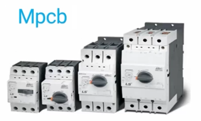
MPCB: A motor protection circuit breaker, or MPCB, is a specialized electromechanical device that can be used with motor circuits. MPCB has an inbuilt OLR (Overload Relay) + Short circuit connected to the Trip coil. In event of a fault like an overload OLR coil will sense and give the command to trip coil to trip. In event of a Short circuit fault, the SC coil will energise inside MPCB and trip the circuit breaker.


Most VFD manufacturers recommend a maximum distance between drive and motor. Most distances are between 100 to 300 ft. Installing output reactors between the drive output and the motor reduces the rate of voltage rise (increases the voltage rise time). This limits the reflected wave amplitude and extends the allowable distance for motor cables.
Type 1 Coordination requires that under short circuit conditions, the contactor or starter shall cause no danger to persons or installation and may not be suitable for further service without repair and replacement of parts. In this case, significant damage is allowed to the contactor/ starter (e.g. contact welding, burning, or disintegration) and the overload relay (e.g. component harm or heater element burn-out).
Type 2 Coordination requires that under short circuit conditions, the contactor or starter shall cause no danger to persons or installation and shall be suitable for further use. The risk of contact welding is recognized, in which case the manufacturer shall indicate the measures to be taken as regards to the maintenance of the equipment. In this case, the contactor/starter is able to continue use after the occurrence of a short circuit fault. Light contact burning or tack welding may occur provided the contacts are easily separable
Sample
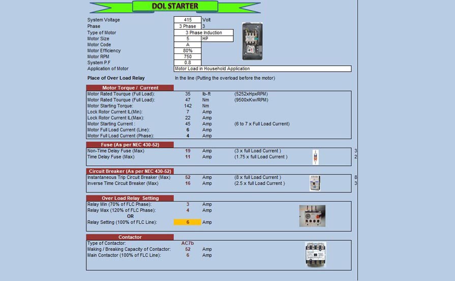
Calculate size of each part of for the system voltage 415V, 5HP three phase house hold application induction motor, code A, motor efficiency 80%, motor RPM 750, power factor 0.8 and overload relay of starter is put before motor.
Motor Rated Torque (Full Load Torque) = 5252xHPxRPM
Motor Rated Torque (Full Load Torque) = 5252x5x750 = 35 lb-ft.
Motor Rated Torque (Full Load Torque) = 9500xKWxRPM
Motor Rated Torque (Full Load Torque) = 9500x(5×0.746)x750 = 47 Nm
If Motor Capacity is less than 30 KW than Motor Starting Torque is 3xMotor Full Load Current or 2X Motor Full Load Current.
Motor Starting Torque = 3xMotor Full Load Current
Motor Starting Torque = 3×47 = 142Nm.
Motor Lock Rotor Current = 1000xHPx figure from below Chart/1.732×415

As per above chart Minimum Locked Rotor Current = 1000x5x1/1.732×415 = 7 Amp
Maximum Locked Rotor Current = 1000x5x3.14/1.732×415 = 22 Amp.
Motor Full Load Current (Line) = KWx1000/1.732×415
Motor Full Load Current (Line) = (5×0.746)x1000/1.732×415 = 6 Amp.
Motor Full Load Current (Phase) = Motor Full Load Current (Line)/1.732
Motor Full Load Current (Phase) = 6/1.732 =4Amp
Motor Starting Current = 6 to 7xFull Load Current.
Motor Starting Current (Line) = 7×6 = 45 Amp

Maximum Size of Time Delay Fuse = 300% x Full Load Line Current.
Maximum Size of Time Delay Fuse = 300%x6 = 19 Amp.
Maximum Size of Non Time Delay Fuse = 1.75% x Full Load Line Current
Maximum Size of Non Time Delay Fuse = 1.75%6 = 11 Amp.
Thermal Overload Relay
Thermal Overload Relay (Phase):
Min. Thermal Overload Relay setting = 70%x Full Load Current(Phase)
Min. Thermal Overload Relay setting = 70%x4 = 3 Amp
Max. Thermal Overload Relay setting = 120%x Full Load Current(Phase)
Max. Thermal Overload Relay setting = 120%x4 = 4 Amp
Thermal Overload Relay (Phase):
Thermal Overload Relay setting = 100% x Full Load Current (Line).
Thermal Overload Relay setting = 100%x6 = 6 Amp

Type of Contactor = AC7b
Size of Main Contactor = 100%X Full Load Current (Line).
Size of Main Contactor = 100%x6 = 6 Amp.
Making/Breaking Capacity of Contactor = Value above Chart x Full Load Current (Line).
Making/Breaking Capacity of Contactor = 8×6 = 52 Amp.
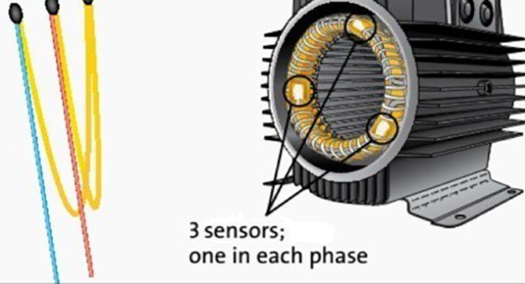
Thermistor motor protection.
A thermistor is a small non-linear resistance sensor, which can be embedded within the insulation of a motor winding, to provide a close thermal association with the winding. It’s made from a metal oxide or semiconductor material.
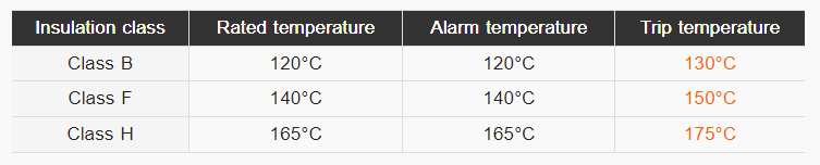
Typical temperature level settings used on rotating electrical machines
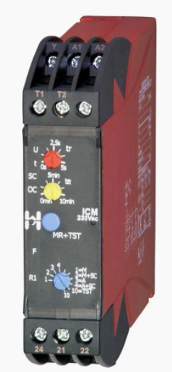
Thermistors are connected to a TPR and the resistance are monitored by a thermistor protection relay (TPR) and, when the sharp change in resistance is detected by the thermistor protection relay (TPR), it operates
Motor Protection General Topics
Generally, motor protection is about the below topics
Overload protection
Short Circuit protection
Phase Failure protection
High Voltage protection
Low Voltage protection
Unbalanced Voltage protection
Phase Reversal protection (Not common)
Voltage Surges
