Terms
Pre-commissioning refers to the individual equipment trial/testing while there can be several pieces of equipment, each with different input-output/parameters and make ready for commercial production, and make a smooth starting of commercial production and reach the rated capacity.
Commissioning refers to an overall (combined or all the machine rather than just equipment) trial and then starting Production with raw materials input, and getting the end product.
Post-Commissioning means solving outstanding punch points (Punch list) after the plant has been handed over to the client.
De-commissioning: At the end of the life cycle of a plant, de-commissioning. De-commissioning means taking out of active use and dismantling an industrial plant.
Punch List: A punch list (also called a snag list, deficiency list, or punch out list), is “a document listing work that does not conform to contract specifications, usually attached to a certificate of substantial completion.” Put simply, it is a list of to-do’s that need to be completed before a project can be considered finished.
Dry Run: A dry run (or a bench test) is a testing process where the effects of a possible failure are intentionally mitigated. For example, an aerospace company may conduct a “dry run” test of a jet’s new pilot ejection seat while the jet is parked on the ground, rather than while it is in flight.
FAT: The factory acceptance test (FAT) refers to the functional test that is performed by the vendor upon completion of the manufacturing process to prove the equipment has the same specification and functionality indicated in the datasheet, specification and purchase order.
SAT: Site Acceptance Testing (SAT) provides an opportunity for final confirmation that the performance experienced during the Factory Acceptance Testing (FAT) is repeated after the systems are installed onsite, ensuring nothing has changed or was damaged during shipment and installation.
Prerequisite
Mechanical
The prerequisite for Electrical commissioning is checking the mechanical completion and checking the FAT or SAT of mechanical vendors. For example, the pump curve may be measured again on site to confirm that it still meets technical requirements
Grounding and Binding
Grounding and bonding checks before the power are applied integrity of the grounding system and bonding system needs to be verified. We want to check this before the first power is applied because if there are any issues during energization this is the
the system that will direct hazardous energy to the ground and
protect the equipment and protect any people that are working in the area
grounding and bonding checks are typically confirmed visually or can be measured with a multimeter measuring the resistance of bonds to ensure low impedance bonding to all metallic surfaces in place so following that the first power can be applied
Polarity
With power polarity checks we want to confirm that the cables are installed correctly so there is no cause damage to the equipment or cause any safety hazards
AC phase check
checks before three-phase systems are energized phase checks are completed to verify the installation of each electrical phase in the proper order if three-phase power is installed backwards called phase rotation the system may rotate in the wrong direction
Test Based on Documents
IO test sheet
sample:
.tg {border-collapse:collapse;border-spacing:0;} .tg td{border-color:black;border-style:solid;border-width:1px;font-family:Arial, sans-serif;font-size:14px; overflow:hidden;padding:10px 5px;word-break:normal;} .tg th{border-color:black;border-style:solid;border-width:1px;font-family:Arial, sans-serif;font-size:14px; font-weight:normal;overflow:hidden;padding:10px 5px;word-break:normal;} .tg .tg-glna{background-color:#fffe65;text-align:left;vertical-align:top} .tg .tg-0lax{text-align:left;vertical-align:top}| No. | Control Cabinet | Drawing No. | Rack ID | I/O Address | Description | TagID | PLC Map Address | Point to point | PLC | Processor Functionality |
|---|---|---|---|---|---|---|---|---|---|---|
| 1 | Main MCC | E201 | -FL00A0 | DI_00_0.00 | Main Incomer C/B | TR_ACB_OK_I | DI_00[0].00 | x | x | x |
| 2 | Main MCC | E202 | -FL00A0 | DI_00_0.01 | MCC Internal Equipment & JB’s Feed | TR_INT_CBCL_I | DI_00[0].01 | x | x | x |
| 3 | Main MCC | -FL00A0 | DI_00_0.02 | DI_00[0].02 | – | – | – | |||
| 4 | Main MCC | E202 | -FL00A0 | DI_00_0.03 | CC1 Feed Circuit Breaker Closed | TR_CC1_CBCL_I | DI_00[0].03 | x | x | x |
| 5 | Main MCC | E205 | -FL00A0 | DI_00_0.04 | CC2 Feed Circuit Breaker Closed | TR_CC2_CBCL_I | DI_00[0].04 | x | x | x |
Motor Test
Sample:
.tg {border-collapse:collapse;border-spacing:0;} .tg td{border-color:black;border-style:solid;border-width:1px;font-family:Arial, sans-serif;font-size:14px; overflow:hidden;padding:10px 5px;word-break:normal;} .tg th{border-color:black;border-style:solid;border-width:1px;font-family:Arial, sans-serif;font-size:14px; font-weight:normal;overflow:hidden;padding:10px 5px;word-break:normal;} .tg .tg-z0iz{background-color:#fffc9e;text-align:left;vertical-align:top} .tg .tg-0lax{text-align:left;vertical-align:top}| Drawing | Tag ID | Description | Power | Voltage | Current | Starter | MCCB | Trip | Earth Leakage | Contactor | Overload | Thermistor + PTC + W/H | Starter | Isolator/FCS | Dist. MCC | Cores/ | Cable | Rotation Test | Continuity | Earth Test | Earth Leakage Breaker |
|---|---|---|---|---|---|---|---|---|---|---|---|---|---|---|---|---|---|---|---|---|---|
| Ref | MCC | [kW] | [V] | [A] | Type | (MERLIN GERIN) | (MERLIN GERIN) | (MERLIN GERIN) | (TELEMECANIQUE) | (TELEMECANIQUE) | (TELEMECANIQUE) | (ROCKWELL) | [m] | phase | |||||||
| E242 | Q01 | MCC Main Incomer C/B | 672.08 | 400 | 1054.42 | MCCB | NW1200SX | Micrologic 6 | 25 | 2 | 300 mm2 Circular TPS XLPE Single Core Cu | x | x | x | x | ||||||
| E243 | Q02 | CC1 Power Feed (3C + N) | 16.08 | 400 | 25.26 | MCCB | NS160SX | STR22SE | VIGI – MH 29211 | 273 | 1 | 70 mm2 Aluminuim XLPE 4 Core | x | x | x | x | |||||
| E244 | Earth Cable | 100 | 1 | 120 mm2 Circular TPS XLPE Single Core Cu | – | x | x | N.A | |||||||||||||
| E245 | Q03 | MCC Fishbone Feed | 40 | 400 | 62.83 | MCCB | NS100SX | TM63D | VIGI – MH 29211 | 26.3 | 1 | 16 mm2 Circular TPS PVC 4C+E Copper | x | x | x | x | |||||
| E246 | P111 | Services 1 Ring Main | 35 | 400 | 95.11 | MCCB | NS100SX | MA100 | VIGI – MH 29211 | N/A | 2P Isolator | 56 | 1 | 185 mm2 PVC/PVC 4C + E Aluminuim | – | x | x | N.A | |||
| E247 | P112 | Services 1 Ring Main | 35 | 400 | 95.11 | MCCB | NS100SX | MA100 | VIGI – MH 29211 | N/A | 2P Isolator | 22 | 1 | 185 mm2 PVC/PVC 4C + E Aluminuim | – | x | x | – |
Machine Sequence
Based on SFC sequential function chart, the PLC code must be the same as SFC documents. Note that SFC applies to the assembly line (Not the process control)

Loop Check
Loop checking is the process that confirms the components are wired correctly and also helps to ensure that the system is functioning as designed.
Hot and Cold Loop check
Cold loop checking is done without powering up, ie the wiring integrity is tested through loop resistance and continuity check. Whereas the hot loop checking is done by simulation of the automation controller (PLC, DCS) and the I/O.
During the Hot loop check all the calibration, HMI or SCADA visualization, Alarm checks will be checked too.
protection relay testing
protection relays are used within electrical systems to monitor voltage and current and provide rapid response to safe the system should there be any fault detected.
The first thing that needs to be done is to verify that the correct settings have been applied to the relay
Other important tests
There are more tests that need to be done but are not necessary by the Electrical Automation dept. Below are some of these tests:
Interlock checks- hypot stands or insulation test – battery discharge tests- Electrical building test (MEP)
Classification
Classic classification has 3 types A-B-C. Type a deficiency would be anything that must be corrected immediately before proceeding any further with any commissioning steps. Type B deficiency is something that does need to be corrected before handover to the owner but doesn’t necessarily impact immediately the function or operation. Type c deficiency would be minor in nature that doesn’t need to be corrected now it could even be corrected after handing over to the owner.
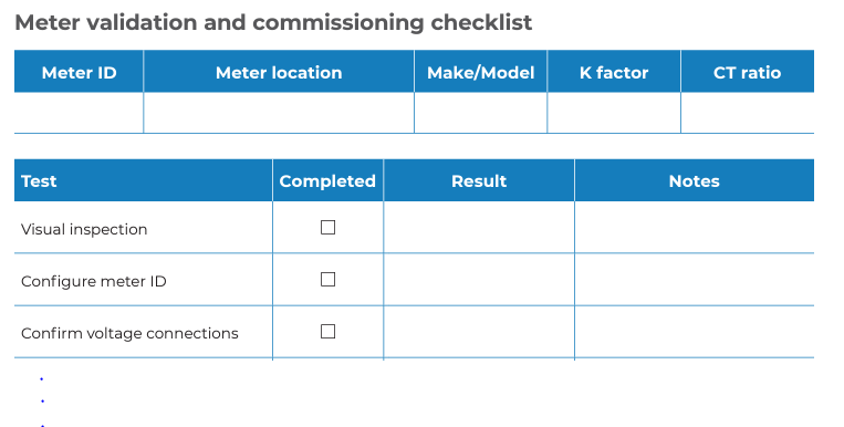
Sample for Metering project
Installation and commissioning tests and checklist
The following commissioning tests need to be completed by the metering supplier or contractor to ensure the metering system is installed correctly:
- Perform a visual inspection of the hardware, including the installed CTs and meter wiring.
- Configure meter identifier and/or IP address.
- Confirm voltage on correct sequence: V1-Red, V2-White, V3-Blue, VN-Black.
- Confirm the CTs are of the correct ratio and polarity, and correctly located to record the required power flow:
- Confirm the loads on any CTs are within the correct limits.
- CT on correct phase: I1-Red, I2-White, I3-Blue.
- CT on correct direction: arrow pointing to the load.
- For split core CTs check for proper closing position.
- Configure the CT settings in the meter and confirm they match the installed CTs.
- Check the meter date and time settings.
- Apply a known load to the circuit and record and confirm: phase voltages
- phase currents
- phase power factor
- active, reactive, and apparent power.
- For multi-phase installations, confirm the relationships between voltages and currents are correct and that phase rotation is standard at the meter terminals.
- Verify the energy management and monitoring system is correctly reading energy usage data from the meter.
- Re-seal any tamper-proof seals on energy billing meters post-commissioning.