What a safety instrument system is, how it is constructed, and how does it play an important role in keeping our chemical refining and other manufacturing plants running safely?
Chemical petrochemical mining, gas compression, and many other types of plants and manufacturing facilities can be very dangerous places to work due to the presence of different types of risks like fire, explosion, tank overflow, gas release, or chemical exposure.
The only way to COMPLETELY eliminate these risks is to not build or operate these types of plants, but that’s not practical. In order to MINIMIZE these risks, process control systems are installed to maintain a safe operation of the plant, assisted by a robust alarm detection and reporting system and operated by trained, qualified personnel. But often these measures alone cannot reduce the risk of injury, fire, explosion, or other risks to a tolerable level.

Regardless of the types of risks the process design itself, the basic process control system, alarms, and operator intervention provide the first layers of protection for the process. Each of these layers provides approximately tenfold or greater protection to the process plant than the layer below. In the process design, care is taken to specify lines, equipment, and valves with the right sizes, materials of construction, and proper accessories. The basic process control system is installed with the appropriate instruments, controls, and monitoring logic to allow the plant to be operated within the safest ranges for pressure, temperature, and flow rate. Alarms are configured to allow the operators to react to abnormal conditions and take corrective actions before a risk becomes an accident.
Even with all of these layers of protection in place, the risks may still be too great to prevent an accident from happening.
In order to mitigate risks, OSHA, the Occupational Safety and Health Administration and several companies in the chemical industry, along with ISA and other professional groups, embraced the idea of defining risks not as isolated processing line or tank risks, but as risks associated with processing functions as a whole. Standards ISA 84 and IEC 61508 were developed around the concept of functional safety. Later, these standards, ISA in the US and IEC in Europe were harmonized in a single standard. (ISA-84/IEC-61511)
The way functional safety would be addressed in a plant in order to reduce functional risks was to install a separate, well-designed safety instrumented system.
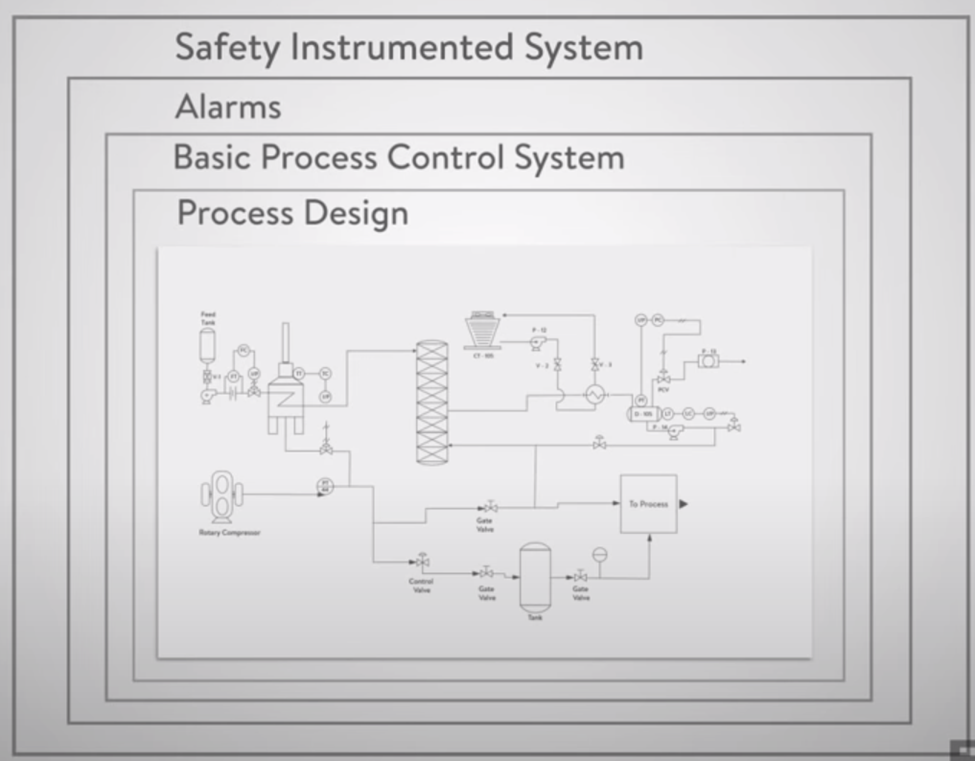
The Safety Instrumented System, or SIS, represents an additional layer of protection above the first three layers discussed previously. This layer should provide at least a ten fold decrease in the risk of the operation. This decrease can be called a Risk Reduction Factor or RRF of equal to or greater than ten.
As we have seen, many levels of protection are required to reduce the risk of an operation to a Tolerable risk level.
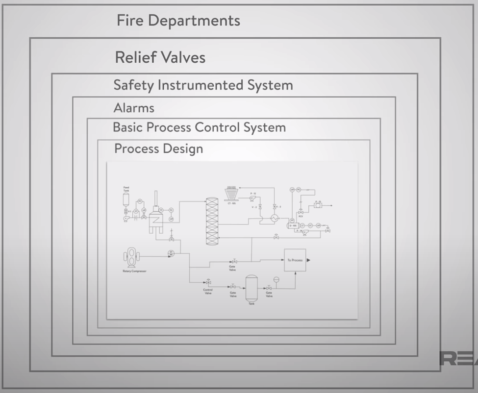
The level of Tolerable risk must be determined by each individual company, but there are benchmarks for many industries such as chemical, oil and gas, food and beverage, and others. Overall, the chemical industry has a Fatal Accident Rate, or FAR of 4. Driving a car has FAR of 40. Fatal Accident Rate is just one way that overall risk can be measured, and in addition to the layers discussed so far, others can be added to reduce the overall risk even greater, like physical protection devices such as relief valves and dikes, and plant and community response teams like fire departments.
Safety Instrumented System (SIS)
A safety instrumented system is comprised of sensors, logic solvers, and final control elements for the single purpose of taking the process to a safe state when predetermined conditions are violated.
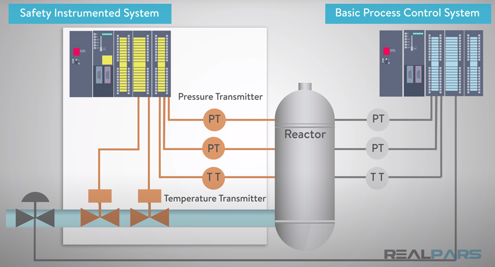
This means that the Safety Instrumented System, or SIS, is a separate set of devices from the basic process control system. In order to provide a risk reduction factor of greater than 10 times, it cannot be interlinked with the basic process control system and any of the shortcomings of that system.
The SIS is designed around individual functions in the plant called Safety Instrumented Functions, or SIF. For short, the logic solver takes the SIS inputs and determines what the state of the SIS outputs should be.
For that SIF, consider this process for transferring a liquid from a tank to a reactor. Normally, the flow controller, which resides in the basic process control system can easily make the transfer of liquid in a very controlled repeatable manner. When the reactor level reaches a high alarm point, the flow is stopped by shutting the control valve. In order to keep the closed tank from overpressurizing, let’s define our safety instrumented function as reactor overpressure protection. Now let’s add the pieces of the SIS that are required to implement the components required for this function.
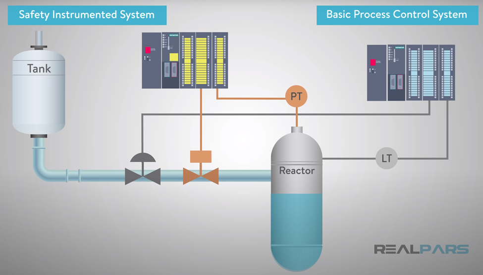
As you can see we keep the basic process flow control loop in place operating as it normally does. But now we add a pressure sensor logic solver and a positive shutoff valve to stop the flow. Independent of the flow controller and the basic process control logic, we have provided an independent layer of protection against the reactor overpressure. This improves the overall safety of the process. In designing a safety instrumented system, the design team must do a detailed risk analysis identifying all of the potential risks and deciding which of the risks require a safety instrumented function to be defined.
A detailed risk matrix can be used to identify the level of risk that is tolerable and at what point a function requires a SIF to be defined. This can be done qualify.
Visit risk Risk Assessment
Probability of Failure on Demand PFD
Even a safety instrumented system has a probability to fail. What if the pressure sensor in the previous example does not detect the high-pressure condition? What if the isolation valve does not close when it’s told to? The probability that a device, whether input, output, or logic solver, will fail, causing the SIF to not respond when called upon is called the Probability of Failure on Demand or PFD.
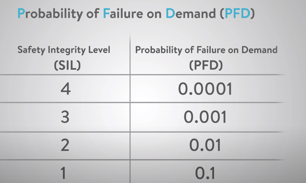
For instance, a pressure regulator has approximately a one in ten or one times ten to the negative power of one. The probability of failure in a year’s time failure of an isolation valve is about one in 100 or one times 10 to the negative power of two. These values can be obtained from vendor data for specific devices or from industry databases of typical PFDs for each type of device. When we design an overall safety instrumented system for each safety instrumented function, we need to determine the overall probability of failure on demand, or PFD for each function that is required. If we determine the PFD should be less than 0.01, then our SIF needs to be designed to a Safety Integrity Level SIL of two.
We can look up the PFD values for each of the devices and PLC elements we would like to use, but to determine the overall PFD for an individual SIF usually requires a computer program. The higher the safety integrity level, the more reliable the safety instrument function will be.
Another way to reduce risk is to add redundancy. Redundancy adds cost but generally will increase the reliability of the system and reduce risk. A one out of two systems will provide a greater level of safety response than a simplex system. A two out of three fault tolerance system can provide a greater level of safety response than a one out of two systems. While the two out of three systems may be more reliable, it may be installed at a much higher cost than one out of two systems.
When designing a safety instrumented system, the ISA-84/IEC-61511 standards prescribe a methodology for developing and documenting the system. Certain design principles should be followed such as not allowing online changes to a PLC, requirements for testing the SIF, and management of change process for making any changes to the system once the design has been approved to review past accidents and fatalities that have led to a new way of looking at risk in a processing plant.
Alarm Management Process
- The Alarm Table includes details about the alarm priority (typically no more than 3 in my experience), why the alarm has been activated, and the message that should be displayed to the end user.
- The alarm journal is a log/DB that records all the alarms that have been triggered in a system over a given period. It includes details such as the date, time, and type of alarm that was triggered, as well as any associated data, such as the specific parameters that were exceeded and the corrective action that was taken. The alarm journal can be used to identify trends, identify potential issues, and ensure that alarms are being responded to in a timely manner.
- Give Access to the alarm page is typically restricted to those who are authorized to view it.
Alarm management is the process of organizing and managing alarm systems to ensure they are running efficiently and effectively. It includes the design, implementation, and maintenance of alarm systems and the development of policies and procedures to govern their use. This process also includes the evaluation of alarm performance, identification of areas of improvement, and implementation of corrective actions. Alarm management is essential for reducing false alarms and improving the safety of a facility.
- Establish Clear Alarm Procedures: Before any alarms are set up or commissioned, ensure that the necessary procedures are in place to ensure that any alarms are managed in a safe and effective manner. This includes setting up a clear process for responding to alarms, assigning roles and responsibilities, and setting up an alarm log for tracking and reporting.
- Define Alarm Criteria: When setting up an alarm, be sure to clearly define the criteria that must be met for the alarm to be triggered. This includes setting specific trip points, time delays, and other conditions.
- Install Alarm Devices: Once the criteria for the alarm have been established, it is time to install the necessary alarm devices. Depending on the type of alarm, this could include a variety of sensors, actuators, and other control devices Including software.
- Test and Validate: Once the alarm devices have been installed, it is important to properly test and validate the system to ensure that it is working as intended. This includes testing the alarm devices, their connection to the system, and the system’s response to a triggered alarm.
- Train Personnel: After the alarm system has been installed, it is important that staff members are trained in the proper use of the system. This includes how to activate and deactivate the system and respond to an alarm. Training should also include basic first aid and emergency response protocols.
1. What is Safety in Design (SiD)?
The Concept: It is the process of identifying risks during the design phase and “designing them out” so the people building, operating, or maintaining the plant don’t get hurt. The “Hierarchy of Controls” (Memorize this): When you find a risk, you must try to fix it in this specific order:
- Elimination: Get rid of the hazard completely (Best).
- Substitution: Replace it with something safer.
- Engineering Controls: Add guards, sensors, or interlocks (This is where you fit in).
- Administrative Controls: Warning signs, procedures.
- PPE: Helmets, gloves (Worst/Last Resort).
2. What is HAZOP?
Definition: Hazard and Operability Study. It is a structured workshop where you look at a P&ID (Piping and Instrumentation Diagram) and ask “What if…?” questions using “Guide Words.”
- Guide Words: No Flow, Reverse Flow, High Pressure, High Temperature.
- Example: “What happens if the dosing pump keeps running but the water stops?” (Answer: The pipe explodes or gas creates a hazard).
