
Thread networking protocol
Thread is a secure and reliable mesh networking protocol built on the IEEE 802.15.4 standard. It is designed to enable products that require low-power, secure, and reliable device-to-device communication. It is optimized for applications such as home automation, building automation, asset tracking, medical device monitoring, and much more. The Thread protocol is maintained by the Thread Group, a non-profit organization of companies committed to enabling IoT products that are based on the protocol.

Jargon
in a Thread topology, every device is responsible for dynamically changing its role from thread leader to thread router. This is an essential feature of the Thread protocol, as it allows the network to be self-organizing. Each node will assume the role that is best suited to its current environment, in order to maintain the stability and optimal performance of the network.
Thread networks can be either wired or wireless. Depending on the application, Thread can be used to create a wired network or a wireless mesh network.you can connect two computers using a Cat6 cable and Thread. The maximum range of a Thread network is around 200 meters. This range can be extended with the use of Thread Routers and other network optimization techniques.
A Thread Border Router (TBR) is a router that connects a Thread network to other IP networks, such as Wi-Fi or cellular. The TBR is the gateway between the Thread network and the internet, and provides network address translation, security, and other services. Thread Border Routers also allow devices to access services in the cloud, such as device management and data analytics.
The Thread Leader is a Router that is responsible for managing the set of Routers in a Thread network. It is dynamically self-elected for fault tolerance, and aggregates and distributes network-wide configuration information. The main difference between a Thread Leader and a Thread Router is the routing capability. Thread Leaders do not have the ability to route traffic, while Thread Routers can route traffic both within a Thread network and to other IP networks. Additionally, Thread Routers are capable of providing network address translation, security, and other services. A Thread Leader and Router are selected automatically based on the network topology. Each Thread network has one Leader, which is elected based on the network’s rules. A Router is selected based on the network’s needs, such as providing access to other IP networks or providing services in the cloud.
In the Thread protocol, a child is a device that is connected to a Thread parent (the node that is responsible for providing the connection to the network). The Thread parent assigns each of its children a unique address and is responsible for routing packets between them. A Thread child is not responsible for routing packets, but instead communicates with its parent, and other nodes on the network, through its parent. A sample of a Thread child could be a light switch, a thermostat, or a motion sensor. These devices are connected to the Thread parent and can communicate with each other, as well as send and receive commands from the Thread parent. you can say that a Thread child is a sensor or actuator connected to a Thread parent.
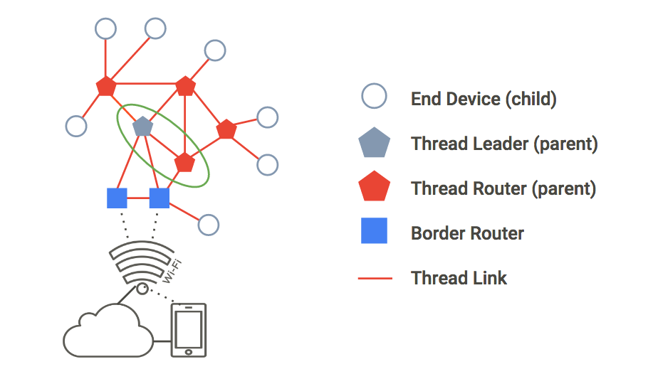
In Thread communication, each parent is assigned a unique 16-bit address. The address is used to identify each node in the network and is used for routing messages.
EUI: Unique Identifier is what we need to connect to an Openthread device,
CC or Channel Control, is a function used in wireless communication to manage the channels. and applies to all device in the network
Thread Simulation Software
/openthread/build/examples/apps/cli/ot-cli-ftd 1
This command launches the FTD(Full Thread Device) version of the OpenThread Command Line Interface (CLI). It allows users to interact with their OpenThread devices to configure, debug, and interact with their networks.
dataset init new
This command is used in the OpenThread CLI to initialize a new dataset on the network. It can be used to configure a network’s parameters such as channel, PAN ID, master key, mesh local prefix, PSKc, networks key, and so on. Once initialized, the new dataset will become active and the network will be able to communicate with other OpenThread nodes.
dataset commit active
This command is used in the OpenThread CLI to commit the active dataset. It activates the parameters in the active dataset and makes them available to the OpenThread network. After committing the active dataset, other OpenThread nodes will be able to see the updated parameters in the network.
ifconfig up
This command is used in the OpenThread CLI to enable the network interface associated with the OpenThread node. Once the network interface is up, the device can communicate with other OpenThread nodes.
thread start
This command is used in the OpenThread CLI to start the networking protocol on the OpenThread node. Once the thread protocol is started, the device will be connected to the OpenThread network and can start communicating with other nodes.
state
This command is used in the OpenThread CLI to show the current state of the OpenThread node and its network topology.
Modbus
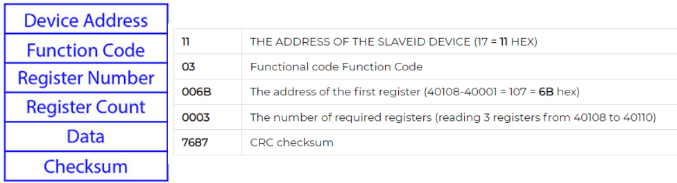
A Modbus slave address is an identifier that is assigned to each device on a Modbus network. Each device must have a unique address in order for the network to function properly. The address is typically an 8-bit number, ranging from 0 to 255. This allows for up to 256 devices on a single network.
Modbus function codes are codes that are used to indicate the type of action or data being requested or sent over a Modbus network. These codes are 8-bit values, ranging from 0 to 255, and can be used to request data from a device, send data to a device, and more. Common Modbus function codes include READ_HOLDING_REGISTERS, WRITE_MULTIPLE_REGISTERS, and READ_DEVICE_INFORMATION.

Modbus registers are memory locations used to store data for use in a Modbus network. Modbus is a communication protocol used for industrial automation, and the registers are used to store data related to the system, such as input/output status, device settings, and more. The data stored in these registers is accessible by any device on the network.

Sample
Modbus RTU requires a 120 ohm termination resistor at the end of each segment of the network. This resistor helps to reduce reflections from the end of the network and improve signal integrity.The maximum length of a single segment of a Modbus network is typically around 1,200 meters
Modbus Transparent
A Modbus Transparent Device is a device that allows transparent communication between Modbus devices without altering the Modbus protocol. It acts as a bridge or repeater, relaying Modbus messages between devices without modifying or interpreting the data. It is typically used to extend the communication distance between Modbus devices or connect multiple Modbus networks.
Modbus RTU to TCP Gateway Device:
A Modbus RTU to TCP Gateway Device is a device that translates Modbus RTU (Remote Terminal Unit) protocol, which uses serial communication, to Modbus TCP (Transmission Control Protocol) protocol, which uses Ethernet or TCP/IP for communication.
Modbus Device Standalone mode
In a standalone mode, a Modbus device operates autonomously, performing its designated functions without relying on external commands or control. It typically has its own logic and internal configuration that allows it to operate without constant communication with other devices or a central control system.
QModMaster a god master software
Addressing: e.g. Address “0500” according to the manual is for Kwh. It references a holding register address, although the 0x03 is not mentioned. However, note that the actual Modbus address you’d use in a Modbus request would be offset depending on zero-based or one-based addressing conventions. If “0500” is zero-based, you’d be accessing Modbus address 501 (in one-based terms) using function code 03.
BACnet
BACnet (Building and Control Network) is the global data communication standard for building automation and control networks.
BACnet is an open, network communications protocol for building automation and control systems. It is an ASHRAE, ANSI, and ISO standard for connecting disparate systems and distributing real-time information over many different networks. BACnet is intended to provide a common language for computerized building automation systems and is used in a wide variety of applications from controlling electricity use to controlling lighting, HVAC, and access control.
Object
Each object has some properties which relate to the character of that object e.g for Analogue input object properties are Unit, Interval etc (Link)
Bacnet objects are like pieces in a puzzle. They fit together to help build a network of devices that can all send and receive information from each other. They help make sure the information is sent to the right place, and are even responsible for how the information is used. Most experts and sources indicate there are 23 standard BACnet objects used in building automation systems.
Binary Input/Binary Output/Binary Value/Analog Input/Analog Output/Analog Value/Averaging/LifeSafety/Zone/LifeSafety Point/Multi-State Input/Multi-State Output/Multi-State Value/Loop/Calendar/Notification Class/Command/File/Program/Schedule/Trend Log/Group/Event/Enrollment/Device
Service
A service in BACnet is a predefined set of operations or commands that are used to access and control building automation systems (BAS). The services can range from reading a value like voltage from a device, to setting the operating mode of an HVAC system.
An example of a service in BACnet is the Read Property service. This service is used to read the value of a property from an object that resides on the BACnet network. For example, if you wanted to read the voltage of a light sensor, you would use the Read Property service to do so. Other services include Write Property, Who-Is, and I-Am.
Back net service could be Confirmed (Reply required like read) and Unconfirmed (Who is, Im and Time sync)
Media
BACnet IP: is based on the Internet Protocol (UDP). The BACnet router transmits messages between BACnet networks. It might connect a BACnet/IP system to an MS/TP system. The Default IP Address of the BACnet Router is 192.168. 2.101, Subnet Mask is 255.255. 255.0.
BACnet MSTP: RS-485, BACnet MS/TP is a token passing protocol that uses a signal, called a token, to authorize devices on the network to communicate. MS stands for “Master-Slave” and TP stands for “Token Passing.” It is mainly used for connecting field devices to a controller
BACnet MSTP (Master Slave Token Passing) is a protocol for exchanging messages between control systems or devices over serial and Ethernet networks. It is a multi-master protocol that uses token passing to regulate access to a communications network. The Master node passes “tokens”, or messages, to other devices on the network, and these tokens give the receiving node permission to access the network. The Master node can also initiate communication with other devices on the network and also listen to device broadcast requests.
BACnet IP address is IP : MAC address e.g. 192.168.0.1:0xBAC0 – (BACnetIP Configuration)
Master – Slave
0-127 addresses are for master devices and 128-254 addresses are reserved for slave devices. Only master
devices can initiate requests and are part of the token passing. Slave devices cannot initiate requests for data, they only reply to messages from other master devices and are not part of the token passing. It is better to cluster all the devices at adjacent addresses to minimize unwanted Poll From Master (PFM). Refer to Optimize MAC Address & Max Master section to reduce PFM to a minimum.
M-Bus-
M-Bus (Meter-Bus) is a European standard for remote gas, water and electricity meter readings. It requires two wire cables to provide power and communication simultaneously. M-Bus supports daisy-chaining devices and remote reading using a handheld unit connected to a PC. It is a reliable system that does not require a dedicated communication line or repeater.
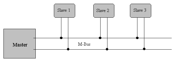
The M-Bus is a hierarchical system, with communication controlled by a master (Central Allocation Logic). The M-Bus consists of the master, a number of slaves (end-equipment meters) and a two-wire connecting cable: see Figure 8. The slaves are connected in parallel to the transmission medium – the connecting cable.
M-Bus is a typical single-master bus, in which the master requests and picks up the data from the slaves. With a primary address space of 250 addresses, up to 250 slaves can be connected to a master.
The question for the maximum possible cable length in M-Bus networks is not easy to
answer since several parameters are critical.
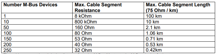
A two-wire standard telephone cable (JYStY N20.8 mm) is used as the transmission medium for the M-Bus. The maximum distance between a slave and the repeater is 350 m; this length corresponds to a cable resistance of up to 29 W . This distance applies for the standard configuration having Baud rates between 300 and 9600 Baud, and a maximum of 250 slaves. The maximum distance can be increased by limiting the Baud rate and using fewer slaves, but the bus voltage in the Space state must at no point in a segment fall below 12 V, because of the remote powering of the slaves. In the standard configuration, the total cable length should not exceed 1000 m, to meet the requirement of a maximum cable capacitance of 180 nF.
The M-Bus is polarity-independent and needs no line termination resistors at the end of the cables.
As Mbus logical 1 corresponds to a signal level of 36 V DC, a logical 0 is represented by 24 V DC. as a result, common USB devices and a software on my PC can NOT make my PC a Master
PiiGAB M-Bus Setup Wizard is a free tool to test, search, and configure M-Bus meters.
IEC 870-5 is an international standard for data communication protocols used in energy management systems.
Meaning of the Fields in M-Bus:
C Field (Control Field, Function Field)
A Field (Address Field)
CI Field (control information field)
Primary and Secondary Address in M-Bus:
The slave devices can be addressed using either a short primary address, which is an integer typically in the range 1-250, or the secondary address, which is a unique 16-byte string. The primary address is used for communication and if there is more than 1 same address, then a fault occurs. the secondary address is unique. and could be used during commissioning. No need to go in front of the device for finding the correct address.
Communication at the application layer in MBus is a message-oriented approach. The MBus application layer defines a set of standardized message types that are used for specific purposes, such as requesting meter readings, configuring parameters, or performing diagnostics.
Each message in the MBus protocol consists of several data fields, including information about the sender and receiver, the message type, and the data payload.
Some common MBus standard message types include:
- “Data Request” message: The master device sends this message to request metering data from a specific slave device. The message specifies the type of data requested (e.g., energy consumption, water flow), and the slave device responds with the corresponding data.
- “Data Response” message: This message is sent by the slave device in response to a data request from the master device. It contains the requested metering data, such as energy readings or volume measurements.
- “Configuration” message: This message type is used to configure parameters of the slave device, such as the measurement interval or reporting format. The master device can send this message to set specific configuration settings on the slave device.
- “Alarm” message: When a predefined condition or event occurs in the slave device, it can send an alarm message to the master device. This message alerts the master device about important events, such as meter tampering attempts or network connectivity issues.
How to request for specific data from master
