Electrical Building Design: Electrical building design involves the planning and design of the electrical systems within a building. This includes the design of power supply systems, the construction of wiring systems, and the installation of electrical outlets, and other components. In order to ensure safety and compliance with applicable codes and regulations, all electrical building designs must be approved by a certified electrical designer prior to construction. As part of this process, the electrical designer must determine the power needs of the building, the type of wiring and wiring systems to be used, and the location of electrical outlets. In addition, the electrical designer may also need to oversee the installation of the actual wiring and inspect the completed system to ensure that all code requirements are met.

Total Connected Load (TCL): Total Connected Load (TCL) is the total electrical load or demand that is connected to a power supply system. In MEP (Mechanical, Electrical and Plumbing) systems, the TCL typically includes loads such as lighting, HVAC, motors, pumps and other equipment that require electrical power to operate.
Single Line Diagram (SLD): A Single Line Diagram (SLD) in MEP is a graphical representation of the electrical connections within a system. It is used to show the main components and their wiring connection to each other. The SLD will show how the power travels from the incoming power source, through power distribution centers, to end-use devices such as lights or motors.

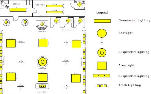
Lighting Layout: It shows the location of light fixtures and switches along with the circuit connections. It is a useful tool for planning electrical installations in buildings.
Raw Power Layout: Raw Power Layout diagrams show the distribution of primary power supply and electrical distribution equipment from a main power supply source. It is typically used in large industrial applications or as part of an MEP system design to ensure a safe and reliable power supply. The Raw Power Layout will typically include the main transformer, circuit breakers and main switches, as well as any transfer switches or control devices.
Both Raw and UPS layout is required
An electrical plan includes the following:
cable routing diagram – the positioning of the electrical cabinets, cable types and their routes, the positioning of every electrical equipment and device in the building
electrical distribution wiring diagram – devices in the electrical cabinet and their wiring
bill of material
topological drawing – the form taken by the network of interconnections of the circuit components
Conduit Layout: Conduit Layout diagrams are used to show the wiring pathways within a building. A Conduit Layout diagram will show the route taken by electrical cabling within a structure, the type of conduit used and the size of the conduit. Common conduit types include electrical metallic tubing (EMT), rigid conduit, and flexible conduit. The Conduit Layout diagram is an important part of an MEP system design and helps ensure the electrical installation is safe and code compliant.

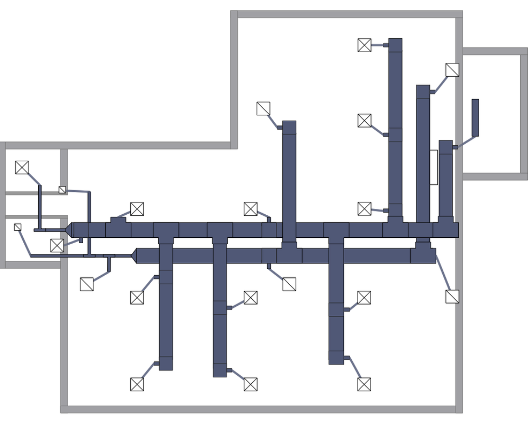
A/C Layout: An A/C Layout diagrams is a type of MEP system layout that shows the path of air ducts, blowers, vents, and other components of an air conditioning system. The A/C Layout diagram will show the location of all the components, the size of the ducts, the location of the filters, and the direction of air flow. The A/C Layout is an important part of an MEP system design as it helps ensure a well-functioning air conditioning system.
Control Wiring Layout: Control Wiring Layout diagrams are diagrams that show the wiring of the control devices that are part of an MEP system. This can include wiring for lighting, air conditioning, fire alarm, and other electrical systems. The Control Wiring Layout diagrams will show the connections between the various components and devices, and will help ensure that all the electrical systems are operating correctly.
Note that Ladder diagrams show how a system works and are used for troubleshooting purposes. Wiring diagrams show where equipment is and how it is connected.
CCTV PAS: CCTV PAS stands for Closed Circuit Television (CCTV) Power, Alarm and Surveillance systems. These systems are used to monitor and protect property and people from vandalism, theft, and other malicious activities. CCTV PAS systems typically include cameras, motion detectors, alarms, and access control systems. The CCTV PAS system is part of an MEP system design and helps to ensure a safe and secure environment.
What is BMS
BMS, or Building Management System, is a computer-based system used to control, monitor, and optimize a building’s electrical, mechanical, and safety systems. It is often used in commercial buildings, hotels, hospitals, and other large complexes. The BMS can automate and streamline tasks such as temperature, lighting, and energy management, fire and safety systems, security, and HVAC (heating, ventilation, and air conditioning).
BMS can integrate with many systems Like EMS, Fire Alarm, Lighting etc.
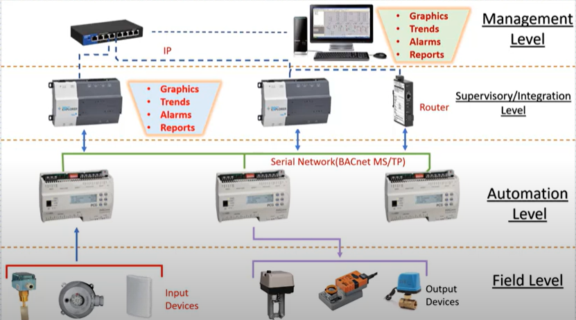
Component Of BMS:
1- Workstation or Management Level – It is the computer level include HW and SW
2- DDC Level: which is the control level. (Microprocessor Level). DDC stands for Direct Digital Control, and is a type of technology used in Building Management Systems (BMS) to monitor and control building systems. DDC is based on the use of programmable controllers—often referred to as “intelligent controllers”—which combine measurement, control, and communication functions in a single unit. These controllers provide the ability to closely monitor and adjust elements of a building’s internal environment, such as temperature, air pressure, and humidity. The controllers also allow for the automatic response to certain events that are sensed.
3- Field Level : Sensors


Workstation sample software (Honewell EBI), Niagara EX, Niagara N4 etc. Note that at supervisory level we can have some sort of monitoring but not a good solution for large buildings and workstation PC is required
Also Please note that based on the controller the supervisory/integration may not be required and the controller talks BACnet IP directly.

DDC Direct Digital Control
DDC is very similar to PLC with some local I/O. Programmable Logic Controllers (PLCs) are industrial-grade controllers BUT Direct Digital Control (DDC) systems are more feature-rich, as they include advanced features such as trending, alarming, remote monitor and control, and energy management. DDC systems also use intelligent controllers, which combine the sensing, control, and communication functions into one unit.
ASCs are a type of DDC technology. An Application Specification Controller (ASC) is a type of high-level controller used to monitor and control systems in a building. An ASC is typically connected to a number of sensors, switches, and meters, and acts as the centralized source of information and control for the rest of the system. The ASC can be programmed with specific instructions or logic that determines how the system will respond to changes in the environment. ASCs can also be used to monitor alarms and perform maintenance tasks. They use for specific applications like Package units. the communication protocol is BACnetMSTP
AASC is advanced series of ASC and usually supports both BACnet IP and MSTP. Note that They use for specific applications also flexible models exist as well.
BC or Building Controller also known as Global Controller is used for routing information between different controllers. It is a general-purpose device capable of carrying out a variety of building automation and control operations. most of the BC does not have any point capacity and if it has point capacity there is not much difference between flexible AASC and BC (Sample company).
Panels:
DGP: Data Gathering Panel (Control level Exit Here) The wiring is similar to PLC panel (Sample Wiring Diagram)
MCC: Motor Control Cabinet
JB: Junction Box
MSB: Main SwitchBoard
Documents for BMS
IO List
Riser Diagram
Shows DGP Location / Equipment Connected to DGP / Details about Network Connection (Link)

BOM (Bill Of Material)
ICN
An Integrated Communications Network (ICN) streamlines all of your building infrastructure into one easy-to-manage environment. When a business makes an investment in a building they tend to install and manage disparate infrastructure in order to run their HVAC, Lighting, Fire, Lift and Security systems.
(Sample Company)
The ICN typically consists of four layers of networking, such as the field equipment layer, the protocol layer, the gateway layer, and the enterprise interface layer.
A generic Set
Electrical projects may not include every type of diagram, but they usually follow a clear process—starting with broad system overviews and moving to detailed component designs. In areas like networking and power systems, these drawings turn complex ideas into practical plans. They show power distribution or data network layouts and become more detailed as the project moves forward.
1- A conceptual diagram (Block Diagram) is a simplified overview of an electrical system, showing the main components and their relationships on a single page. It avoids specific details like numbers or equipment specs, focusing on the big picture for easy understanding. somehow it is similar to PFD.
2- A Single Line Diagram (SLD) visually simplifies the flow of power or data in a system. In power systems, it shows how electricity moves from the source through components like switchgear, panelboards, and transformers to final loads such as lights and motors. In communication systems, it maps how data travels from field devices through gateways, switches, and routers to a central server or cloud.
3- A multi-line diagram, also called a three-line diagram, shows each conductor or phase in an electrical system separately. It includes all connections, terminals, and wiring details for components. This makes it very useful in industrial settings, such as motor control circuits and power distribution systems.
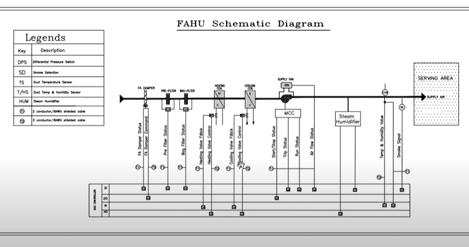
3.1- A schematic diagram, on the other hand, focuses on the functional relationships and logical flow between components, rather than their physical layout or wiring. While both types of diagrams use lines to represent wires and connections, schematic diagrams are mainly used in PCB (printed circuit board) design, where understanding circuit behavior is important. In contrast, multi-line diagrams are commonly used in industrial and electrical engineering for installation, maintenance, and troubleshooting.
4- Wiring diagrams show the physical layout and electrical connections in a device or piece of equipment. Unlike schematic diagrams, they highlight the actual placement of wires, terminals, connectors, and components, often focusing on a single device. This detailed view is essential for technicians and engineers during installation, troubleshooting, and maintenance.
5- Layout drawings show how building systems are constructed and coordinated. They provide details about the location of equipment, fixtures, and electrical or mechanical systems. These diagrams also specify the size, dimensions, and placement of components to ensure proper fit and function. Additionally, they illustrate the routing of pipes, ducts, conduits, and cables, showing how these elements connect and align with the building’s design.
5.1 A cabinet layout drawing is a detailed, to-scale representation of an electrical or control cabinet, illustrating the internal arrangement of components like PLCs, relays, circuit breakers, terminals, and wiring pathways. It includes physical dimensions, equipment positioning, and a human outline for scale to ensure design specifications and ergonomic standards are met before fabrication and installation.
