A 415V, 1600A main switchboard is a substantial electrical installation, typically used for large commercial or institutional facilities. To estimate the likely size of a community center that would require such a switchboard, we can analyze the maximum power capacity and compare it with typical building loads.
Power Capacity Calculation
- Voltage: 415V (three-phase)
- Current: 1600A
The apparent power (S) in kilovolt-amperes (kVA) for a three-phase system is calculated as:S=3×V×IS=3×V×IS=1.732×415×1600=1,151,488 VA=1,151 kVAS=1.732×415×1600=1,151,488 VA=1,151 kVA
This means the main switchboard can handle up to approximately 1,150 kVA of load.
Typical Building Loads
- For commercial buildings and community centers, a rough estimate is often 60–100 VA per square meter for mixed lighting, HVAC, and general power, but this can vary widely depending on usage (e.g., presence of kitchens, gyms, auditoriums)1.
- Using a conservative average of 80 VA/m², the floor area supported can be estimated as:
Area=1,151,000 VA80 VA/m2≈14,388 m2Area=80 VA/m21,151,000 VA≈14,388 m2
Contextual Comparison
- A 1,150 kVA supply is typical for large buildings such as schools, mid-sized shopping centers, or large community centers with multiple halls, gymnasiums, and support facilities2.
- For example, a 1 MVA transformer (close to 1,000 kVA) is often used for large community or sports centers, small hospitals, or multi-story office buildings3.
Practical Considerations
- The actual usable area could be less if the building has high-demand equipment (e.g., commercial kitchens, large HVAC systems, or specialized facilities).
- Diversity and demand factors may reduce the actual peak load, but the switchboard is sized for maximum expected demand, including future expansion41.
Summary Table
| Switchboard Rating | Approx. Max Load (kVA) | Typical Supported Area (m²) | Example Facility Types |
|---|---|---|---|
| 415V, 1600A | 1,150 | ~14,000 | Large community centers, schools, small hospitals, multi-level commercial buildings |
Conclusion
A 415V, 1600A main switchboard would typically be installed in a large community center—likely supporting a facility in the range of 10,000 to 15,000 square meters, depending on the specific load profile and building usage. This size is consistent with major venues, multi-purpose halls, or centers with extensive amenities and high electrical demand23
Key Additional Calculations for Switchboards
1. Power Loss Calculation
- Power losses in circuit breakers, busbars, and cables must be calculated to ensure the switchboard operates efficiently and within temperature limits. Each component’s power dissipation is determined based on its rated and actual current, and the total power loss is summed for the entire board1.
2. Earthing (Grounding) Calculation
- Proper earthing is essential for safety. Calculations determine the size of earthing conductors to ensure they can safely carry fault currents. Formulas such as those from IEC 60364 and IEEE 80 are used to size earth bars and conductors based on expected fault current and duration2.
3. Short-Circuit Withstand Calculation
- The switchboard and its components must be able to withstand the mechanical and thermal stresses during a short-circuit event. Calculations verify that busbars, connections, and protective devices can handle the maximum prospective short-circuit current for the required duration.
4. Protection Coordination
- Selectivity and discrimination studies ensure that protective devices (breakers, fuses) operate in a coordinated manner, isolating only the faulted section without unnecessary disruption to other circuits.
5. Voltage Drop Calculation
- Ensures that voltage levels at the load terminals remain within acceptable limits, accounting for the length and size of busbars and cables.
6. Mechanical and Structural Calculations
- The physical design must support the weight and mechanical forces of all components, especially during fault conditions.
7. Degree of Protection (IP Rating) and Internal Separation
- Calculations and checks to ensure the switchboard meets required ingress protection (IP) ratings and internal separation forms for safety and reliability, especially for high-current boards3.
8. Dielectric (Insulation) Withstand Test
- Ensures that the switchboard can handle overvoltages and insulation requirements, typically verified through testing but based on design calculations.
9. Moisture and Condensation Control
- In some environments, calculations and provisions for anti-condensation heaters are made to prevent moisture build-up, which can damage components4.
Summary Table
| Calculation Type | Purpose |
|---|---|
| Power Loss | Ensure thermal limits are not exceeded |
| Earthing | Personnel and equipment safety during faults |
| Short-Circuit Withstand | Mechanical/thermal integrity during faults |
| Protection Coordination | Reliable and selective fault isolation |
| Voltage Drop | Maintain voltage quality at loads |
| Mechanical/Structural | Physical safety and support |
| IP Rating/Internal Separation | Prevent ingress, enhance safety and reliability |
| Dielectric Withstand | Insulation safety |
| Moisture/Condensation Control | Prevent corrosion and electrical failure |
These calculations, in addition to load and heat rise, are essential for a safe, compliant, and reliable switchboard design
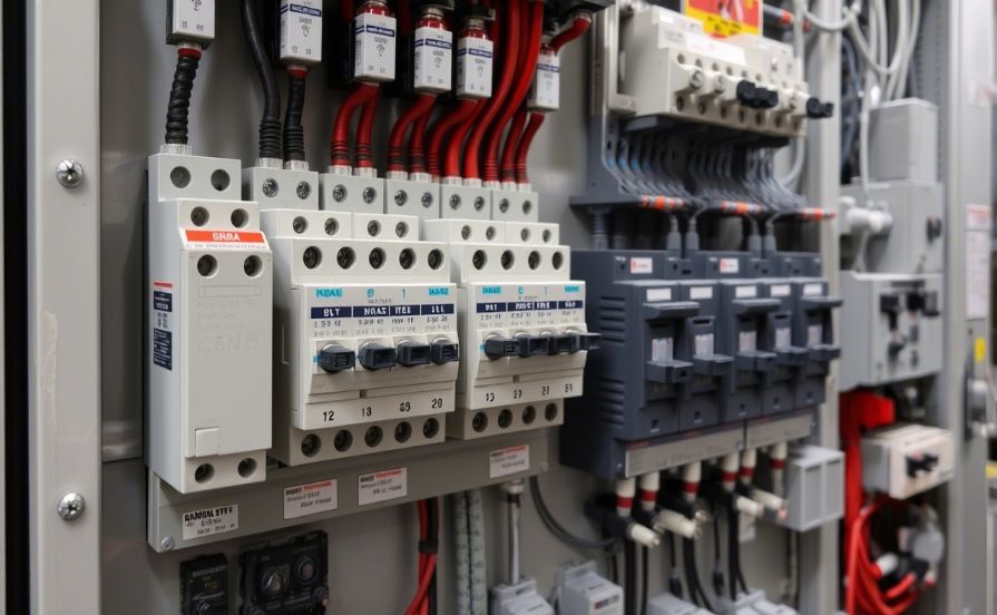
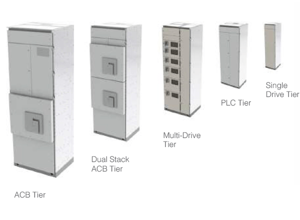
Tier: Switchboards have horizontal rows called “tiers” where devices like circuit breakers or feeders are mounted. They can be single-tier (one row) or multi-tier (stacked rows), making better use of space and fitting more devices.
| Term | Meaning in Switchboard Context |
|---|---|
| Tier | A horizontal row or level for mounting devices inside a switchboard |
| Single-tier | One row of devices (e.g., breakers, feeders) |
| Two-tier | Two rows of devices, one above the other |
| Multi-tier | More than two rows, maximizing device density |
| Tier connection | The point where bus stack connects to the main bus, can be single or double per phase depending on current rating |
Lift off panels: Lift-off panels are removable panels on a switchboard, unlike hinged doors that swing open. These panels detach completely for easy access to internal components, simplifying maintenance, inspection, or modification.
Standards such as AS/NZS 3000:2018 Wiring Rules recognize lift-off panels (sometimes referred to as “lift-off type doors”) and specify that, regardless of panel type, minimum clearance requirements around the switchboard must be maintained for safety and accessibility.
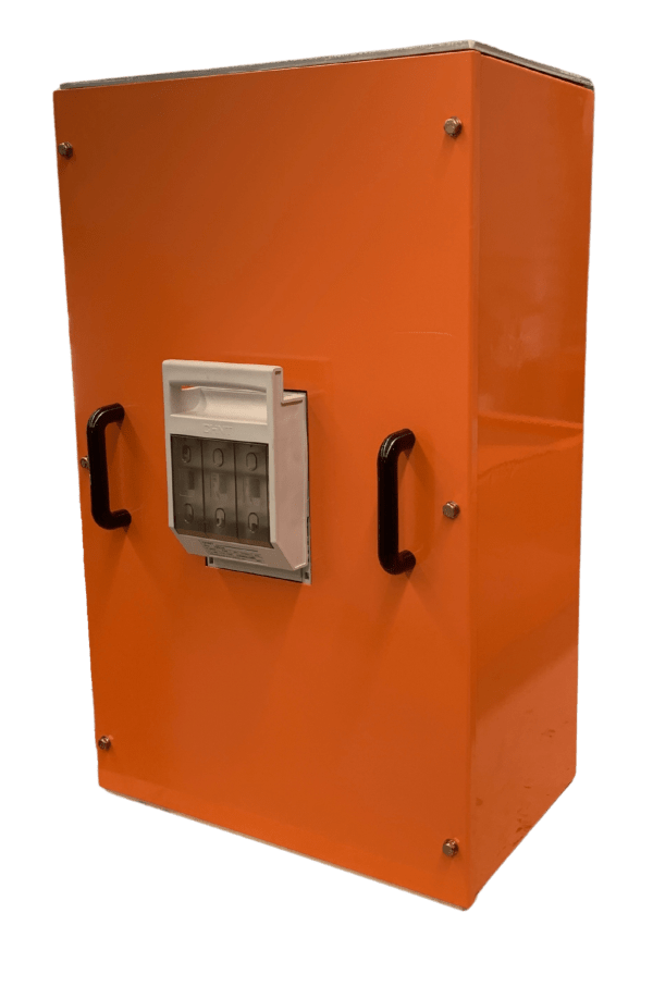
Plinth: A Plinth is a square or rectangular metal base used to support an enclosure. Plinths are used to raise an enclosure so service access is easier or minimize risk of flooding at the installation site. Plinths can be open frame or enclosed with sheet metal sidewalls.
Form in AS/NZS 61439
Electrical switchboards in Australia and New Zealand are designed in accordance with AS/NZS 61439, a standard that outlines ‘forms of internal separation’.
Often referred to as Form 3b, Form 4a, etc.,
these designations define the level of compartmentalisation within the switchboard. Think of it as creating separate, protected zones for different live components such as busbars, circuit breakers, and connection terminals. This separation is crucial for safety
during maintenance by protecting personnel from live parts. It also prevents
a fault in one section from spreading, ultimately improving the switchboard’s overall reliability and operational continuity. The higher the form number, the more stringent the separation, offering greater protection for more critical applications.
The Two Key Fault Tests
Short-Circuit Withstand Test: Ensures the switchboard’s frame, busbar supports, and component mountings can endure the intense magnetic forces of a short-circuit without damage. Arc Fault Containment Test: Ensures the enclosure contains the explosive force and molten metal of an internal arc fault, keeping doors shut to protect nearby personnel.
In electrical design, discrimination (also known as selectivity or coordination) ensures that only the protective device immediately upstream of a fault trips. This isolates the smallest possible area, preventing a minor issue in one circuit from causing a widespread outage. It can be achieved by coordinating the time-current curves of circuit breakers and fuses so the device closest to the fault always reacts faster. For guidance, they refer to standards like AS/NZS 3000-2.5.7. To ensure a safe and reliable power supply, they use specialized software like ETAP or PowerCad or ELEK Cable Pro.
