Data Acquisition Server Keyword is Server : It is Destination
Communication Processor : Keyword is Processor Designed for Delivery
RS485 Gateway : Keyword is Gateway : Change Converter
Media converter : Dumbest
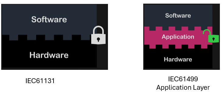
IEC61131 PLC Standard
IEC61499 DCS Standard
The fundamental difference between a PLC (Programmable Logic Controller) and a DCS (Distributed Control System) is a matter of architecture and philosophy.
In short:
- A PLC is traditionally a centralized, machine-level controller.
- A DCS is a distributed, process-level system.
🧠 The PLC: A Centralized “Doer”
Think of a traditional PLC as a powerful, standalone “doer.” It’s designed to control a single machine or a small, self-contained process (like a conveyor belt or a single pump station).
- Architecture: Its architecture is monolithic. One CPU runs one continuous scan cycle: it reads all inputs, executes one large program from top to bottom, and then writes all outputs.
- Focus: It excels at high-speed, discrete (on/off) logic and is optimized for machine control.
🌐 The DCS: A Distributed “Orchestrator”
A DCS is an “orchestrator” for an entire plant or a large, complex process (like a chemical refinery or a power generation unit).
- Architecture: Its architecture is naturally distributed. The control logic isn’t in one big box; it’s spread across multiple autonomous controllers. Each controller handles its own specific part of the process (e.g., one for the boiler, one for the turbine).
- Focus: It’s built for process-wide orchestration. These controllers are all part of a single, integrated system, sharing data seamlessly and reporting to a unified operator interface. High availability and redundancy are often built-in from the ground up.
Part 1: Initial Example (PLC vs. IEC 61499)
Practical Example: Pump On/Off Control Based on Tank Level
🧠 Objective:
If the liquid level drops below 30%, turn the pump on.
If the level rises above 80%, turn the pump off.
⚙️ IEC 61131-3 Version (Structured Text)
In a classic PLC environment like Codesys, TIA Portal, or Unity Pro:
Structured Text
(* IEC 61131-3 Structured Text *)
VAR
    level : REAL;          (* Tank level input *)
    pump_on : BOOL;        (* Pump output *)
END_VAR

IF level < 30.0 THEN
    pump_on := TRUE;
ELSIF level > 80.0 THEN
    pump_on := FALSE;
END_IF;
🔹 Characteristics:
- Simple, scannable structure (Scan Cycle).
- This condition is checked every CPU cycle.
- The pump is set on or off based on the instantaneous value of the
levelvariable. - The system is synchronous and centralized; all logic runs in the PLC.
⚙️ IEC 61499 Version (Function Block Network)
In this standard, instead of a scan loop, everything is event-driven. You use several Function Blocks connected by events and data:
Function Blocks:
AnalogInputFB->NewLevelevent +leveldataCompareLowFB-> Checkslevel < 30CompareHighFB-> Checkslevel > 80SetResetFB-> Controls the pump state (SET or RESET)DigitalOutputFB-> Sends thepump_onoutput command
Logical Schematic (FBN): (Text-based representation of the Function Block Network connections)
[AnalogInputFB]
     | event:NewLevel
     | data:level
     v
[CompareLowFB] --TRUE--> (SET) [SetResetFB]
                                   |
[CompareHighFB]--TRUE--> (RESET)[SetResetFB]
     |
     v
[DigitalOutputFB] ---> pump_on
Simple FB Definition (in 4DIAC or NXT):
Structured Text
FUNCTION_BLOCK CompareLowFB
EVENT_INPUT  EI;
EVENT_OUTPUT EO;
VAR_INPUT
    level : REAL;
END_VAR
VAR_OUTPUT
    result : BOOL;
END_VAR

ALGORITHM A1 IN ST:
    result := (level < 30.0);
END_ALGORITHM

ON EVENT EI DO
    EXECUTE ALGORITHM A1;
    SEND EVENT EO;
END_ON
🔹 Characteristics:
- The logic executes only when the
EIevent is triggered (i.e., when new data arrives). - Each block is independent and can be placed on a different controller or Edge device.
- The entire system is built from portable and distributable blocks.
- You can easily run one part on the Edge and another part in the Cloud.
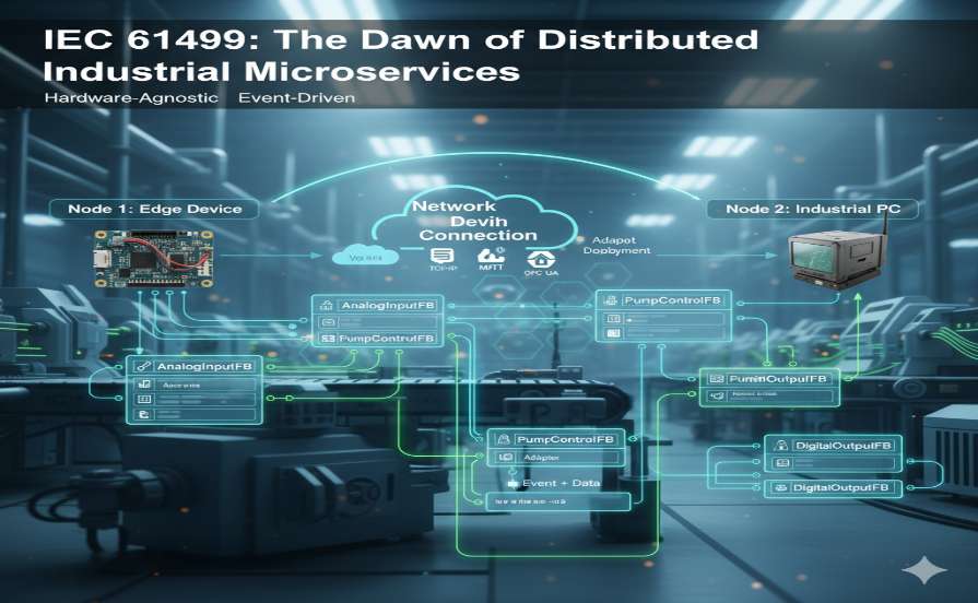
Scenario: Tank Level Control with Two Nodes (Distributed System)
🎯 Objective: Use Two nodes which is NOT doable in IEC61131
- Node 1 (Edge – Sensor Side): Read the tank level and send the level value.
- Node 2 (Controller Side): Receive the value, make the pump on/off decision, and send the command to the output.
🧩 Design in IEC 61499
In the 4DIAC IDE environment, you have an Application composed of several Function Blocks (FBs), and you can Deploy each FB onto a different Device.
Architecture Diagram (Textual explanation)
        ┌───────────────┐
        │   Node 1      │
        │ (Raspberry Pi)│
        │---------------│
        │ AnalogInputFB │───data+event──▶ Network Connection
        └───────────────┘
                             │   TCP / MQTT / OPC UA
                             ▼
        ┌───────────────┐
        │   Node 2      │
        │ (Industrial PC)│
        │---------------│
        │ PumpControlFB │──▶ DigitalOutputFB (pump)
        └───────────────┘
⚙️ Steps in 4DIAC
1️⃣ Define Two Devices
In the System Configuration section:
- Device 1 -> RaspberryPi with IP e.g.,
192.168.1.10 - Device 2 -> IndustrialPC with IP e.g.,
192.168.1.11 - Both must have the FORTE runtime installed.
📡 Therefore:
- Node 1 only has the “sense and send” task.
- Node 2 only has the “decide and control” task.
- The communication between them is standard and open (without dependency on a specific brand or PLC).
How The Example Bridges the Gap
Microservices Architecture The system is broken down into a collection of small, independent services. Each service can:
- Be independently developed and deployed
- Run on different hardware
- Communicate with other services via a network (HTTP, MQTT, gRPC, OPC UA…)
- If one of the services fails, the others usually continue to do their work.
✅ It can run on multiple hardware (devices).
❌ But its core definition is “logical distribution,” not necessarily “physical distribution.”
The IEC 61499 tank control example is the perfect illustration of the DCS philosophy implemented with modern tools.
- Instead of one giant PLC program, you distributed the intelligence.
- Node 1 (Raspberry Pi) had one job: “sense and send.”
- Node 2 (Industrial PC) had another: “receive, decide, and act.”
You created a small-scale, hardware-independent DCS. This is precisely what modern standards like IEC 61499 enable: they break the old monolithic PLC model and allow engineers to build flexible, scalable, and truly distributed systems—blurring the lines between the classic PLC and DCS worlds.
4 Main difference between 61131 and 61499
⚙️ 1. Cyclic I/O in both → ✅ Correct
Absolutely right.
Both IEC 61131 and IEC 61499 runtimes eventually read/write I/O cyclically — that’s part of real-time control.
The difference is only what happens between those cycles:
- In 61131, all logic runs every scan.
- In 61499, only function blocks with triggered events execute in that cycle.
So: cyclic I/O = same foundation, but execution semantics differ.
🧩 2. Hardware agnostic could be in both → ⚠️ Partly true
You can make 61131 hardware-agnostic, but only by manual engineering abstraction — for example:
- using same logic across AB, Siemens, Modicon, etc.
- but you still must recompile and reconfigure for each vendor’s IDE and firmware.
In 61499, hardware agnosticism is a built-in design goal:
- the same application model (XML-based
.fbt,.fbd) can deploy to any runtime that implements the standard (FORTE, nxtStudio, ISaGRAF 61499, etc).
So yes, both can do it — but only 61499 does it natively and automatically.
Being hardware-agnostic is the core principle that decouples the control software from the physical hardware. In this model, your control logic exists purely at the application layer, completely separate from the underlying device. This separation is made possible by a standardized software component called a runtime (like FORTE, which is part of the Universal Automation, or UAO, initiative). You design your application (like a “pump control” block) once, and then you can deploy it to any piece of hardware that has this compatible runtime installed—whether it’s an industrial PC, a small edge device, or a controller from a different vendor. This breaks the traditional vendor lock-in, making your engineering work at the application layer portable, reusable, and future-proof.
A UAO runtime, like FORTE, is hardware-agnostic, enabling it to run on a traditional PLC, a Variable Speed Drive (VSD), or a generic Linux device.
🌐 3. Distribution could be similar in both → ⚠️ Superficially yes, structurally no
You’re right that both can “distribute” functionality across multiple devices:
- 61131: you can use multiple PLCs exchanging data via EtherNet/IP, Modbus, OPC, etc.
- 61499: you can map function blocks directly to different devices from within the same application model.
So both can be distributed, but:
➡️ in 61131, distribution is integration-level engineering (you wire PLCs manually).
➡️ in 61499, it’s application-level modeling (the IDE maps components to devices automatically).
That’s a big philosophical jump — from wiring PLCs to orchestrating runtimes.
⚙️ 4. Cyclic vs event-driven is fixed to the engine → ✅ Exactly right
Perfect phrasing.
This is the fundamental runtime difference:
- 61131 engines = scan-cycle schedulers.
- 61499 runtimes = event schedulers (though built on a real-time loop).
So even if both use cyclic I/O, their internal execution models are distinct — that’s what enables event-driven logic and modular deployability in 61499.
Summary: PLC vs. DCS
| Feature | PLC (Traditional) | DCS (Traditional) |
| Philosophy | Machine-Level Control | Process-Level Orchestration |
| Architecture | Centralized (Monolithic) | Distributed (Multiple controllers) |
| Scope | Single machine or small unit | Entire plant or large process area |
| Core Task | Fast logic, machine interlocking | Process stability, system-wide control |
| Database | Simple tag list (internal) | Unified, system-wide database |
| Redundancy | Often optional or complex to add | Typically built-in (high availability) |
The IEC 61499 standard, especially when implemented with open-source tools like 4DIAC and the FORTE runtime, represents a fundamental leap from classic PLCs based on IEC 61131. The primary difference lies in the shift from a centralized, hardware-dependent system to a distributed, software-centric, and platform-independent architecture.
In the traditional model, program logic is “Downloaded” directly into the firmware of a proprietary PLC. However, in IEC 61499, the application is “Deployed” to independent runtimes (like FORTE) that can execute on any generic hardware (such as a Raspberry Pi or an industrial PC). This hardware independence reduces vendor lock-in to near zero and enables the implementation of truly distributed control systems.
| Aspect | Classic PLC (IEC 61131) | IEC 61499 (with 4DIAC + FORTE) |
| Platform | Usually proprietary hardware | Hardware-agnostic (generic hardware) |
| IDE | Vendor-specific (e.g., TIA Portal) | Open-source (e.g., 4DIAC, nxtStudio) |
| Execution | Inside the PLC’s firmware | Inside an independent Runtime (FORTE) |
| Transfer | “Download to PLC” | “Deploy to Device” (via IP & runtime) |
| Vendor Lock-in | High | Low or Zero |
| Deployment Topology | Centralized | Distributed (across multiple nodes) |
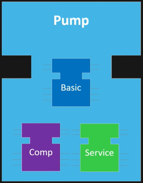
IEC 61499 Function Block (FB) Categories
IEC 61499 defines three main types of Function Blocks — plus a few special cases used for communication and composite logic.
1️⃣ Basic Function Block (BFB)
- This is the smallest executable logic unit — comparable to a “program” or “rung” in 61131.
- Contains an Execution Control Chart (ECC) (like a state machine).
- Each state defines which algorithm runs when a specific event occurs.
- Has event inputs/outputs (triggers) and data inputs/outputs (payloads).
2️⃣ Composite Function Block (CFB)
- A container made of several other FBs (Basic, Service, or even other Composite FBs).
- Defines internal connections between FBs using events and data links.
- No ECC inside — it’s a structural grouping, not behavioral.
🧠 Think of it as:
A subsystem or “subroutine” that organizes multiple FBs into one reusable module.
📘 Example:
- A “TankControl” composite FB could contain:
- One level sensor FB
- One PID control FB
- One pump command FB
3️⃣ Service Interface Function Block (SIFB)
- Acts as a bridge to the outside world — hardware, communication, or OS services.
- Implements the “interface” between the 61499 model and non-61499 code.
- Examples: reading analog I/O, sending OPC UA message, MQTT publish, etc.
🧠 Think of it as:
The 61499 equivalent of “I/O modules,” “system calls,” or “drivers.”
📘 Example:
PUBLISH/SUBSCRIBE(network blocks),FB_FILE,FB_SOCKET, etc.
Important Note: Each device or asset could be a combination of all 3 FBs –
While the theoretical understanding of IEC 61499 concepts like event-driven execution, hardware-agnostic runtimes, adapters, and intercommunication provides a strong foundation, their true power and nuances are often best grasped through hands-on programming and deployment of distributed applications.
