Before selecting a specific circuit configuration, you must choose between a centralized or distributed layout.
• Centralized Layout: Each load is connected directly to the power source (Main LV Switchboard). This is typically used when loads are localized (high unit power) and no flexibility is required,.
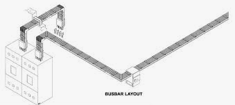
• Distributed (Decentralized) Layout: Loads are connected to sources via a busway (busbar trunking system). This allows power to be supplied to many spread-out loads and offers high flexibility for future changes or new connections
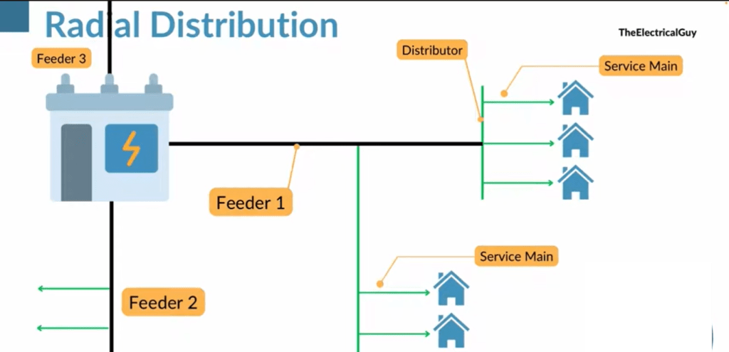
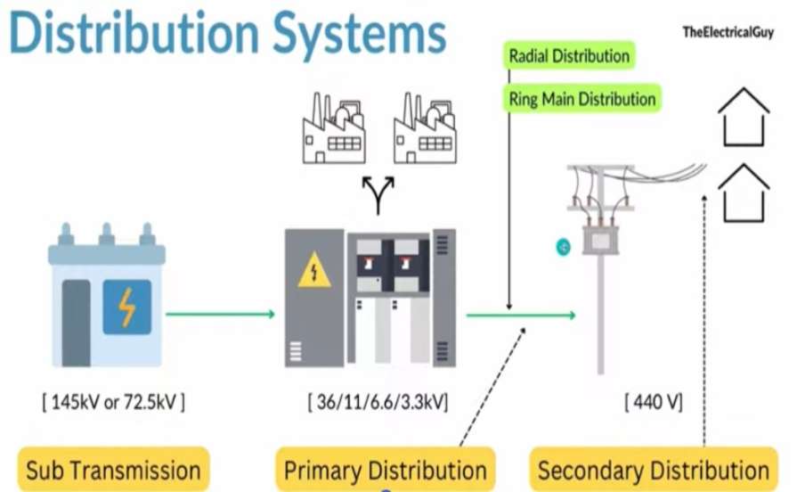
Radial Distribution
Advantages
It is simplest method of the power distribution
It is also the cheapest method available
Disadvantages
Poor reliability
High voltage drop at the tail end of the feeder
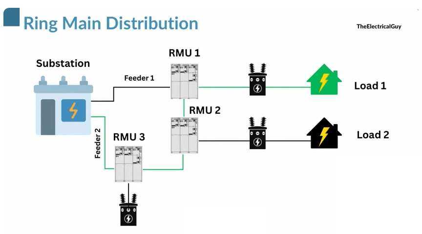
Advantages
- Most reliable for continuity of the supply
Gives better voltage regulation
Disadvantages
Expensive. Requires high investment
| Topology | Best Suited For | Redundancy |
| Single Feeder | Any site topology; localized loads; minimal maintainability required. | None |
| Parallel / Coupled | Any site topology; high sensitivity to disturbances. | Partial or Total |
| Interconnected Busway | Large single-level sites (5,000–25,000 m²); high power demand (≥ 2500 kVA). | Partial or Total |
| LV Ring | Large single-level sites; high power demand (> 2500 kVA); standard maintainability. | High |
| Double-Ended | Any site topology; localized loads; enhanced maintainability required. | Very High |
ETAP
Passive Elements
Before start modelling we need to know about passive elements” in the context of power systems. Unlike generators (active elements), these components simply react to the voltage and current.
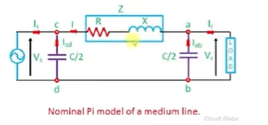
- Transmission Lines: Carry power over distances. Modeled by resistance and inductance (and capacitance for long lines).
- Transformers: Change voltage levels. Modeled by impedance (Z).
- Reactors: Inductors used to limit current or control reactive power.
- Capacitors: Used to correct power factor or support voltage.
Basics: Fundamental Units
This is the most critical part for system modelling. In AC circuits (sinusoidal waves), we don’t just use Resistance; we use Reactance (X). Reactance depends on the frequency (f) of the system (usually 50Hz or 60Hz).Below is the three physical properties of these passive elements
- Resistance (R): Opposes current flow (measured in Ohms).
- Inductance (L): Stores energy in a magnetic field (measured in Henries).
- Capacitance (C): Stores energy in an electric field (measured in Farads).
- For Resistors: V=RI (Voltage equals Resistance × Current)
- For Inductors: V=jXLI
- Where XL=2πfL is the Inductive Reactance.
- The j indicates a 90∘ phase shift (voltage leads current).
- For Capacitors: V=−jXCI
Derived Quantities
In power flow software like ETAP, calculations are often done using Admittance (the inverse of Impedance) because it makes the math for large networks (matrices) easier.
| Name | Symbol | Unit | What it means | Formula / Relation |
| Conductance | G | Siemens (S) | The ease with which DC or real current flows. It is the “real” part of Admittance. | G = 1/R (for pure resistive circuits) |
| Susceptance | B | Siemens (S) | The ease with which AC current flows through a reactor or capacitor. It is the “imaginary” part of Admittance. | B ≈ 1/X (equal to 1/X if Resistance R is zero.) |
| Impedance | Z | Ohms (Ω) | The Total Opposition to current flow. Combines Resistance and Reactance. | Z = R + jX |
| Admittance | Y | Siemens (S) | The Total Allowance of current flow. It is the inverse of Impedance. | Y = G + jB (Also Y =1/Z) |
When you open an editor for a Cable or Transmission Line in ETAP, you will see fields asking for R, X, and Y (or sometimes R and X per unit length). The software needs to convert the physical properties (Length, Material) into Impedance (Z) and Admittance (Y) to calculate voltage drops and power flow.
Active Elements
something dynamic—they either generate power (sources) or consume it to do mechanical work (loads). Unlike passive elements (resistors/cables), their behavior changes based on time, speed, or angle.
When you model a Motor or Generator in ETAP, the software usually asks you for two out of these three inputs, and it calculates the third one automatically using the formulas above.
| Name | Symbol | Unit | What it means | Formula / Relation |
| Complex Power | S | Volt-Ampere (VA, kVA, MVA) | The Total Power flowing in the line. It combines both the working power and the wasted/stored power. Used to size transformers and cables. | S=P+jQ (Vector Sum) |
| Active Power | P | Watt (W, kW, MW) | The Real Power that actually does useful work (e.g., turning a motor shaft, heating a furnace). This is what you pay for on a bill. | P=S×PF (or S2−Q2) |
| Reactive Power | Q | Var (var, kvar, Mvar) | The Magnetic Power. It doesn’t do “work,” but it is required to create magnetic fields in motors and transformers. | Q=S2−P2 |
| Power Factor | PF | Per Unit (pu) or % | The Efficiency of the power usage. It is a ratio of how much “Real” work you get out of the “Total” power supplied. | PF=SP (Cosine of the angle) |
- Common Input: You typically enter Rated kW (P) and Power Factor (PF).
- ETAP Calculation: The software will instantly calculate the kVA (S) and kvar (Q).
Note on “Non-Linear”: refers to devices like Variable Frequency Drives (VFDs) or modern electronics. These don’t just draw a smooth sine wave; they chop up the current, which can create harmonics (noise) in your system. ETAP uses these power equations to estimate their impact.
1- Transmission Line Modelling
A practical comparison of overhead lines and underground cables: The way the conductor is installed (in this case, in the air vs. underground) drastically changes the physics, even if the conductor material is the same.
- Resistance (The Constant)
- Observation: Look at the first row (“Resistance”). The value is 0.134 Ω/mile (or 0.083 Ω/km) across all four columns.
- Materials (Copper) and thickness (500 kcmil) determine resistance. As a result Changing a generic line to a cable won’t change your R value much.
- Inductive Reactance
- The overhead line has a much higher inductive reactance (XL) than the cable. Why: Inductance is driven by the size of the magnetic loop between conductors. To prevent arcing, wires are spaced far apart (8 ft). Inductance is high in this loop. Conductors are tightly bundled. Due to partial cancellation of magnetic fields, inductance is much lower between the opposing phases. ETAP Impact: Cables have a lower voltage drop than overhead lines because the reactance (X) opposes current flow is less.
- Capacitive Reactance
- Capacitive Reactance (XC) is massive (10^6Ω). Capacitance (C) is the inverse of reactance. Cables are essentially long capacitors. Conductors are positive plates, grounded metallic sheaths/shields are negative plates, and insulation is dielectric. Their distance is millimeters (not feet), so their capacitance is huge. ETAP Impact: This is critical for Charging Current.
When underground cables are energized, they generate a lot of Reactive Power (kvar). ETAP underestimates the system voltage if you don’t include the capacitance (or Ground Susceptance B) when modeling a long cable (Ferranti Effect).
- Capacitive Reactance (XC) is massive (10^6Ω). Capacitance (C) is the inverse of reactance. Cables are essentially long capacitors. Conductors are positive plates, grounded metallic sheaths/shields are negative plates, and insulation is dielectric. Their distance is millimeters (not feet), so their capacitance is huge. ETAP Impact: This is critical for Charging Current.
| Parameter | Overhead Line | Underground Cable | Reason |
| Resistance (R) | Same | Same | Depends on metal/size only. |
| Inductive Reactance (X) | High | Low | Wide spacing in air vs. tight spacing in cable. |
| Capacitance (C) | Very Low | Very High | Distance to ground is large (air) vs. tiny (insulation). |
2- Transformer
There are two types of transformers:
- Two-Winding Transformer (2W): The standard type with one input (Primary) and one output (Secondary), used for stepping voltages like 13.8 kV to 480 V.
- Three-Winding Transformer (3W): Has one input (Primary) and two outputs (Secondary and Tertiary) for tasks like stepping down to multiple voltages (e.g., 115 kV to 34.5 kV and 13.8 kV) or mitigating harmonics with a Delta-configured Tertiary winding.
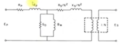
First, we simplify the complex circuit into a single line to make modeling easier.
- Combining Primary and Secondary: Instead of dealing with separate primary (Rp, Xp) and secondary (Rs, Xs) wires, we mathematically “move” the secondary values over to the primary side.
- Single Total Resistance: RT = Rp + Rs/N^2 [N = ns/np]
- Single Total Reactance: XT = Xp + Xs/N^2
- Note : The shunt branch (G0 and BM) is so small compared to the fault current that engineers ignore it to simplify the math.
Dealing with Nameplate Data
When you look at the physical metal nameplate bolted to a transformer, it does not tell you R and X.
- What you get: The nameplate only specifies the total impedance (ZT) and the voltage transformation ratio (N). But ETAP only asks for %Z and the X/R ratio.
- Assumption: Reactance (X) is much larger than the resistance (R). Therefore (XT ~ ZT).
- When engineers (or software programs) only have ZT and N, they must estimate the resistance or X/R ratio by looking at standardized tables published by IEEE.
To be continue by Three Winding Transformer Modelling (42:42)
