Stirred grinding mills are highly energy-efficient comminution machines that, unlike traditional tumbling ball mills, feature a stationary outer shell rather than a massive rotating cylinder. They are generally divided into two main subcategories: vertical and horizontal stirred mills. The horizontal stirred mill category is prominently represented by the IsaMill™, while the vertical stirred mill category includes the VertiMill, Tower Mills, and the Stirred Media Detritor (SMD). Despite their different physical orientations on the ground, both types share the same
fundamental grinding mechanism. Instead of tumbling rock, they utilize an internal rotating shaft equipped with stirrers (such as discs or pins) to vigorously agitate fine grinding media and slurry, efficiently breaking down the ore through high-intensity attrition.
Mechanical
Stress Intensity Theory is the core concept (a mechanical engineering term) and it does not appear in our blog discussion.
Comminution control systems aim to maximize mineral liberation while minimizing energy consumption per ton of ore by balancing stress intensity. In the field of Mineral Processing, mineral liberation refers to Separating valuable mineral grains from the surrounding waste rock (gangue) by grinding.
The automation system constantly adjusts:
- Feed rate
- Slurry density
- Amount of grinding media
Comparison: IsaMill vs. Vertimill Architecture
| Parameter | IsaMill Architecture | Vertimill Architecture |
|---|---|---|
| Physical Orientation | Horizontal layout | Vertical layout |
| Primary Grinding Mechanism | High-intensity attrition via plug-flow | Gravity-induced attrition |
| Internal Operating Pressure | Pressurized (100 to 200 kPa) | Atmospheric / Gravity dependent |
| Internal Classification | Centrifugal product separator (no screens) | Upward flow velocity against gravity settling |
| Typical Media Type and Size | Fine ceramic, silica sand, or inert slag (1 mm to 6 mm) | Coarse steel balls or large ceramic beads (>12 mm) |
| Primary Controlled Variable | Specific Power Draw via targeted media addition | Recycle loop flow ratio and VFD cyclone feed speed |
| Circuit Configuration | Predominantly Open Circuit | Predominantly Closed Circuit with Hydrocyclones |
Feed Rate
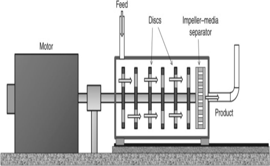
The term “plug-flow dynamic” refers to the internal layout of the machine that allows the slurry to flow uniformly through it, without bypassing the grinding process. A rotating shaft agitates the grinding media between rotating discs that form a “series of grinding chambers” between discs. Each of these individual grinding chambers must be sequentially passed through by the feed slurry after it is pumped into one end of the mill. Because the slurry is forced through these sequential stages step-by-step, it “prevents short circuiting” of the feed. This means that no material can slip through the mill unground.
Specific Energy as the Primary Control Target: Open-circuit operation is the most defining feature of the IsaMill control architecture. IsaMill does not typically require external classifying hydrocyclones to manage product size because it features a patented internal centrifugal product separator that retains fine grinding media in the chamber and allows only appropriately sized product to exit. As a result, traditional recirculating load controls don’t work anymore.
Instead, the fundamental control philosophy of the IsaMill is absolutely power-centric. In order to maintain a strict operating power setpoint, the mill’s specific power draw is the primary variable determining the final product size.
To achieve this, the Programmable Logic Controller (PLC) or DCS continuously calculates the Specific Energy (E) utilizing high-speed analog inputs from the motor variable frequency drive (VFD) or power monitor, alongside mass flow calculations from the feed line. The governing algorithm is programmed as follows :
E = PGross − PNoLoad mFeed
Where:
- E: Specific Energy in kilowatt-hours per ton (kWh/t).
- PGross: Instantaneous IsaMill Gross Power Draw in kilowatts (kW).
- PNoLoad: Pre-calibrated No-Load Power of the mill running empty in kilowatts (kW).
- mFeed: Circuit Fresh Feed Rate in dry tons per hour (t/h), derived from volumetric flow and slurry density.
Other Loops
- The Feed Flowrate Loop: An electromagnetic flowmeter (magmeter) on the fresh ore feed line measures the primary volumetric flow rate. A Proportional-Integral-Derivative (PID) loop uses this data to modulate the centrifugal feed pump’s VFD speed.
- The Slurry Density Loop (Ratio Control): A nuclear density gauge or a Coriolis mass flow meter monitors the specific gravity of the feed line. A Ratio Controller uses this signal to calculate the dry mass feed rate. It mathematically dictates the exact volumetric flow rate of dilution water required. This ensures the dilution water valve injects precisely proportioned water to maintain the correct slurry viscosity before it hits the feed pump.
- The Gland Water Protection Loop: Because the horizontal IsaMill operates under high internal pressure (100 to 200 kPa), a differential pressure (DP) transmitter continuously compares the internal mill pressure against the external gland water supply pressure. If the gland water pressure drops too low, the system triggers a hardwired interlock that instantly trips the main motor. It also isolates the feed valves to protect the trunnion bearings.
