
In this post, we’re going to discuss the commonly used but often misunderstood term ground. There are lots of different names for ground, Such as Earth, Earth ground, neutral, common ground, analogue ground, digital ground and instrument ground, etc. And then you have terms like ground loops.
So what is the ground?
Quite often ground means different things to different people. For example, ground to an electrician might mean something different than ground to electronic engineers.
But first thing first, what is the reason of grounding?
There are lots of reasons for grounding. Proper grounding is a critical safety measure and all electrical systems and installations. We ground the exposed part of electrical equipment so that internal wiring failures don’t raise the voltage potential of these exposed parts to dangerous levels. Every electrical circuit needs to be complete for the current to flow. In many applications, grounding provides a circuit return path. For example, your car chassis is a common ground for all Return current to the battery. So let’s look at some of the different perceptions of ground.

It’s probably safe to say that Earth and Earth Ground are the same things. Earth Ground is the reference point in an electrical circuit that is a direct and physical connection to the earth. Earth ground is the ground that you walk on earth ground is true 0 volts, It is the true zero reference for any and every electricity discussion. You don’t have to go far to see evidence of Earth Ground. You might be able to spot a copper rod in the ground with a heavy wire attached to it. This Earth ground wire runs to your power panel and ultimately connects to all the ground terminals of every receptacle in your house.
What is interesting is the fact that the neutral terminal has a wire that ultimately connects to Earth ground as well. Notice that we’ve used an electrical symbol for Earth Ground. This symbol is probably the most misused in electrical schematics. The symbols used to indicate ground terminals are found in the document IEC 60417 graphical symbols for use on equipment.

As we said earlier, every electrical circuit needs to be complete for the current to flow. In many applications, the common ground becomes the return path. For example, your car chassis is a common ground for the return current to the battery’s negative terminal. Sometimes you’ll see the Earth ground symbol used incorrectly on electronic schematics. The intention is to symbolize a common ground and it may not be connected to Earth ground.
The below picture is a typical example of a small part of a large electronic circuit housed in a metal chassis.

There are foreground symbols that may or may not be connected to Earth Ground, but they are intended to indicate a common ground point. We do know that if we measure the voltage from point A to any of these common ground points, we will measure +15 volts. Ideally, the circuit would be wired with all return paths to the power supply connected at one point.
Unfortunately, this is not practical most of the time. If points 1 to 4 are not connected to Earth Ground but are connected to a common ground; It would be more appropriate to use the symbol below.
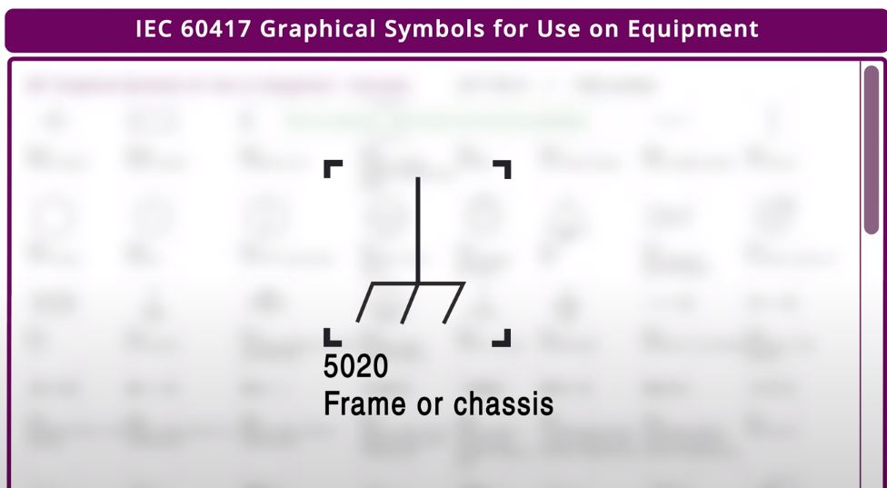
This symbol suggests the points are connected to a frame or chassis terminal. This brings up an interesting question. Are all the components at the common ground potential connected at one point on the frame or chassis, or are they connected to the chassis at multiple locations?
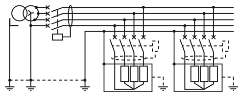
Unfortunately, the schematic does not provide that answer. The schematic does not provide any clue as to physical connections. Industrial schematic drawings will indicate ground points and often provide more detail. But physical connection points are still a mystery. In this example of power distribution in a control cabinet, there are several ground symbols electrically.

This means that all of these points are supposedly at the same voltage potential of zero volts. From these drawings, we can determine where these grounds are connected physically in the control cabinet
This brings us to a term called Ground Loops, A ground loop is an unwanted electrical current path that can cause havoc in equipment or process control systems by introducing unwanted electrical noise. These undesired ground loops are created when two supposedly connected points are not at the same electrical potential. That’s when Ohm’s Law takes over and creates an electrical current flow between these two points. In our example, ground loops can be avoided if all three devices are grounded together at one point.
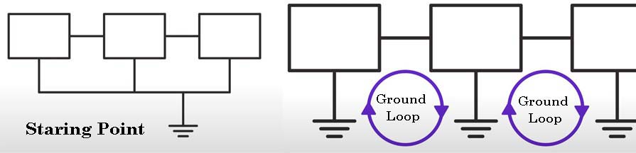
This type of grounded is referred to as starting point grounding. Unfortunately, in large industrial plants, multiple point grounding is the reality and the possibility of ground loops is high. With so many connections reference to the ground within a facility, the chances of needing more than one ground point are great.
OK, let’s review. Quite often ground means different things to different people. Proper grounding is a critical safety measure and all electrical systems and installations in many applications. Grounding provides a circuit return path.
Earth ground is true zero volts. It is the true zero reference for any and every electricity discussion. Earth Ground is the reference point in an electrical circuit that is a direct and physical connection to the Earth. A ground loop is an unwanted electrical current path that can cause havoc in equipment or process control systems by introducing unwanted electrical noise. Ground loops are created when two supposedly connected points are not at the same electrical potential.
TT, TN and IT systems
- T – Grounding.
- N – Connection to neutral.
- I – Isolation.
- C – combined functions: combining the functional and protective neutral wires.
- S – The separate use of functional and protective neutral wires throughout the entire grid.
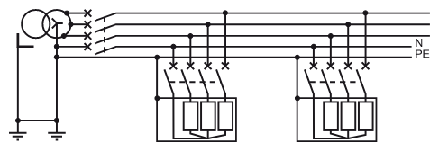
The TT system:
Technique for the protection of persons: the exposed conductive parts are earthed and residual current devices (RCDs) are used
Operating technique: interruption for the first insulation fault
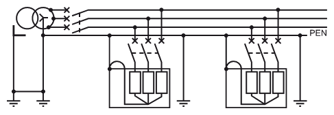
TN system
The TN system:
Technique for the protection of persons:
Interconnection and earthing of exposed conductive parts and the neutral are mandatory
Interruption for the first fault using overcurrent protection (circuit-breakers or fuses)
Operating technique: interruption for the first insulation fault
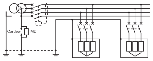
IT system
- Protection technique:
- Interconnection and earthing of exposed conductive parts
- Indication of the first fault by an insulation monitoring device (IMD)
- Interruption for the second fault using overcurrent protection (circuit-breakers or fuses)
- Operating technique:
- Monitoring of the first insulation fault
- Mandatory location and clearing of the fault
- Interruption for two simultaneous insulation faults
https://electrical.theiet.org/wiring-matters/years/2021/84-march-2021/broken-pen/
https://zandz.com/en/library/tn-s-tn-c-tnc-s-tt-it-grounding-systems/
MEN, PEN in Australia
- The MEN system (Multiple Earthed Neutral) is the standard earthing system used in Australia and New Zealand for both domestic and commercial electrical installations.
- In the MEN system, the neutral conductor is earthed at multiple points—from the supply transformer all the way through to the main switchboard of each installation.
- All parts of an electrical installation that require earthing are bonded together (equipotential bonding network) and connected to both the neutral conductor and the mass of earth, ensuring both safety and reliable fault current paths.
- The system enables protective devices (such as circuit breakers and RCDs) to operate quickly during faults, as fault currents can return via the neutral and earth, opening the protective device and removing the hazardous voltage.
- The MEN system is mandated by the AS/NZS 3000:2018 (Australian/New Zealand Wiring Rules) for all new electrical installations.
PEN Conductor
- PEN stands for Protective Earth and Neutral, a single conductor in some earthing systems (commonly in TN-C or similar) that performs both the neutral and protective earth functions.
- In the Australian MEN system, the neutral conductor is multiple earthed and acts as a PEN in the supply side, supporting both neutral return and safety earthing until separation into distinct PE (Protective Earth) and N (Neutral) conductors within installations.
- The PEN is grounded at several points, ensuring that faults are directed safely to earth and minimizing rise of neutral-to-earth voltages across long distances.
Connection of Cable Shield, PE, and N in MEN and PEN Systems (Australia)
The way cable shields, PE (Protective Earth), and N (Neutral) are interconnected depends on the earthing system in use. Below is a breakdown for Australian MEN (Multiple Earthed Neutral), PEN, and cable shield practices.
1. MEN System (Multiple Earthed Neutral)
- PE and N Connection:
At the main switchboard, the PE and N (green/yellow and blue wires) are connected together via the MEN link. This is the only place where intentional connection between PE and N is allowed. The neutral conductor (N) is also connected to the general mass of earth using an earth electrode at this point. - Cable Shielding:
- Cable shields (metallic sheaths, screens, or armouring) are generally treated as an additional protective earth.
- The shield is connected to the earth bar at the supply end (switchboard), not to the neutral. In certain sensitive or signal systems, shields may be connected only at one end to avoid earth loops.
- The shield connection ensures any induced currents or faults travel to earth via the PE/earth network.
Summary:
- Cable Shield → PE/Earth Bar
- PE and N → Connected together only at the MEN link in the main switchboard (never elsewhere)
2. PEN Systems & TN-C / TN-C-S
- PEN Conductor:
Upstream in the distribution network, a single PEN conductor provides both protective earth and neutral functions (e.g., in TN-C systems, common in Australian networks up to the installation entry). - Separation Point:
At the building’s main switchboard, the PEN is split into separate PE and N:- The split creates an earth bar (PE) and a neutral bar (N), which are linked via the MEN link.
- Cable Shielding:
The shield is connected to earth/PE at the main switchboard, not to N or PEN.
In older TN-C runs or if local rules allow, shields may occasionally act as the PEN, but this is generally avoided for safety.
Summary:
- Cable Shield → PE/Earth Bar (never to N directly)
- At the main switchboard: PEN splits into PE and N, which are joined by the MEN link
3. Practical Cable Shielding Practices
- Earthing of Shields:
- Shields of power or control cables are typically terminated at the supply (switchboard) end and bonded to the earth bar for safety and to prevent EMI.
- Sometimes, the exposed part of the shield is wrapped with a dedicated earth wire (PE) and soldered, then heat-shrunk for insulation.
- Shields must not be connected to the neutral bar, except in historic or uncommon installations where the armouring was used as a combined PEN.
Connection Table
| System | Cable Shield | PE (Protective Earth) | N (Neutral) | PE-N Connection |
|---|---|---|---|---|
| MEN (AS/NZS) | To PE/Earth Bar | Separately run, connected at switchboard | Main switchboard, connected to PE via MEN | Only at MEN link |
| PEN (TN-C) | To PE/Earth Bar | Combined as PEN upstream; split at switchboard | Combined as PEN upstream; split at switchboard | Split at switchboard |
Key Points
