
Your FAT test sheet may be complete — and still fail to test the process.
This is something I have seen repeatedly in automation projects. A FAT protocol is often built from P&IDs, electrical drawings, I/O lists and cause-and-effect matrices. These are important. But they don’t necessarily tell us how the process is supposed to behave over time. A valve opening correctly does not prove that a charging sequence works. A pump starting correctly does not prove that the system can safely recover when that pump fails halfway through a sequence. And proving every I/O point does not prove that the automation system can execute the process correctly.
Functional testing is fundamentally a test of behaviour — not just signals.
IEC 62381: The FAT/SAT Question
IEC 62381 provides requirements and guidance for Factory Acceptance Testing (FAT), Site Acceptance Testing (SAT), and related testing activities. But IEC 62381 does not magically tell us how every functional test case should be structured. That structure needs to come from the way the automation system itself has been engineered. And this is where a defined functional architecture becomes extremely important.
┌────────────────────────────────────────────────────────────────────────┐│ TRADITIONAL APPROACH (The Loop-Check Trap) │└────────────────────────────────────────────────────────────────────────┘ ┌─────────────────────┐ ┌──────────────┐ ┌──────────────┐ │ Electrical Drawings │ ──> │ I/O List │ ──> │ Test Sheets │ └─────────────────────┘ └──────────────┘ └──────────────┘ (Physical Only) (Point-to-Point) *Misses dynamic logic!*┌────────────────────────────────────────────────────────────────────────┐│ STRUCTURED APPROACH (ISA-88 & IEC 62381 Integration) │└────────────────────────────────────────────────────────────────────────┘ ┌────────────────────────┐ │ Process Requirements │── (Define "What the plant must actually do") └───────────┬────────────┘ │ ▼ ┌────────────────────────┐ │Functional Architecture │── (Decouple using ISA-88: Unit ➔ EM ➔ CM) └───────────┬────────────┘ │ ▼ ┌────────────────────────┐ │ Control Logic │──(Code structured to mirror physical assets) └───────────┬────────────┘ │ ▼ ┌────────────────────────┐ │ Expected Behaviour │──(Define state transitions:Running, Holding) └───────────┬────────────┘ │ ▼ ┌────────────────────────┐ │ Dynamic Test Cases │── (IEC 62381 Compliant Functional Protocols) └────────────────────────┘
Traditional approach: Electrical drawings → I/O list → Test sheets Structured approach: Process requirements → Functional architecture → Control logic → Expected behaviour → Test cases**
The Problem with Testing from an I/O List
An I/O list tells us things such as:
- DI — Pump Running
- DO — Pump Start
- AI — Tank Temperature
- AO — Valve Position
- Valve Open Feedback
- Valve Closed Feedback
We can test all of them. But consider a simple process: Charge solvent → Agitate → Heat → Transfer Now the questions become very different: What happens if the pump fails during charging? What happens if the operator pauses the process? What happens if a permissive disappears? Does the system hold the process safely? What happens when the operator restarts? What happens to accumulated quantities? What happens if the operator aborts the sequence? These are not simply I/O questions.
They are behavioural and state-transition questions. And this is where the architecture of the control system becomes critical.
Where ISA-88 Fits
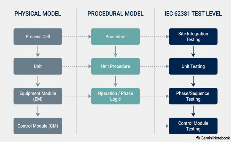
For batch-oriented systems, ISA-88 provides a useful way of separating the physical equipment from the procedural behaviour of the process. The physical model describes what exists on the plant floor:
Process Cell → Unit → Equipment Module → Control Module
The procedural model describes what the process needs to do:
Procedure → Unit Procedure → Operation → Phase
This gives us something extremely valuable for functional testing:
A hierarchy.
Instead of treating the entire automation system as one large block of PLC code, we can identify increasingly higher levels of functionality. And that hierarchy can become the foundation of a structured FAT strategy.

Physical model: Process Cell ↓ Unit ↓ Equipment Module ↓ Control Module
Procedural model: Procedure ↓ Unit Procedure ↓ Operation ↓ Phase
The connection between the two is where functional behaviour is executed — and where meaningful functional tests can be defined.
1. Control Module Testing
Question: Does the individual device behave correctly?
At the lowest level, we verify individual control modules and field devices. For example:
- Valves
- Motors
- Pumps
- VSDs
- Transmitters
- Dampers
- Basic control objects
Typical tests might include:
- Start/stop commands
- Open/close commands
- Feedback verification
- Permissives
- Interlocks
- Fail-safe behaviour
- Loss of signal
- Loss of power or instrument air
- Manual operation
- Alarm generation
The objective is straightforward: Prove that the basic building blocks work correctly. This is an essential foundation. But it is only the beginning.
2. Equipment Module Testing
Question: Can a group of devices perform a useful function?
Now we move beyond individual devices. An Equipment Module may combine several control modules to perform a specific physical function. For example, a heating module could contain:
- Temperature transmitter
- PID controller
- Modulating steam valve
- Permissives
- Interlocks
- Operating limits
The question is no longer:
“Does the valve open?”
It becomes:
“Can this equipment module actually control temperature as designed?”
This is where coordinated functionality, control loops and equipment-level behaviour can be tested.
3. Phase Testing
Question: Can the software execute the intended process action — including abnormal conditions?
This is where functional testing becomes much more interesting. A Phase might perform an action such as: Charge Solvent or Heat to Setpoint. or Transfer Product The obvious test is the happy path:
Idle → Running → Complete
But that is not enough. What happens if something goes wrong while the phase is running? For example:
Running → Hold
What happens to the equipment? Does the pump stop? Does the valve close? Does the process remain in a safe condition? What happens when the operator restarts? And what happens if the operator aborts instead?
Running → Abort → Aborted
These are the scenarios where the real value of functional testing appears.
========================================================================== ACCEPTANCE TESTING: THE "HAPPY PATH" VS. THE "EXCEPTION PATH"============================================================================= THE "HAPPY PATH" (Traditional, Point-to-Point Testing) ┌───────────┐ ┌───────────┐ ┌────────────┐ │ START │ ──> │ RUNNING │ ──> │ COMPLETE │ └───────────┘ └───────────┘ └────────────┘ (Process Runs) (Normal End) *The Danger:* Only verifies that the system works when everything is perfect. It completely ignores physical failures, operator pauses, or safety trips. THE "EXCEPTION PATH" (ISA-88 State-Based Validation / IEC 62381) ┌───────────┐ │ RUNNING │ └─────┬─────┘ │ ▼ (Process Fault / Device Interlock Tripped) ┌───────────┐ │ FAULT │ └─────┬─────┘ │ ▼ (Automatic Safe Shutdown Phase) ┌───────────┐ │ HOLD │ ── (Valves shut, pumps off, └─────┬─────┘ batch progress data preserved) │ ▼ (Operator Diagnoses & Resolves Issue) ┌───────────┴───────────┐ ▼ ▼ (Operator Decision) ┌───────────┐ ┌───────────┐ │ RESTART │ │ ABORT │ └─────┬─────┘ └─────┬─────┘ │ │ ▼ (Resume Process) ▼ (Dump Batch & Flush Unit) ┌───────────┐ ┌───────────┐ │ RUNNING │ │ ABORTED │ └───────────┘ └───────────┘ *The Reality:* Processes rarely fail on the "Happy Path." True commissioning resilience is proven by how the software handles these state transitions.==========================================================================
Happy path: START ↓ RUNNING ↓ COMPLETE
Exception path: RUNNING ↓ FAULT ↓ HOLD ↓ Operator intervention ↓ RESTART / ABORT
The exception path is where functional testing earns its value.
4. Unit-Level Testing
Question: Can the complete unit execute the process as intended?
At the highest level, multiple Equipment Modules and Phases work together to execute a complete process.
For example:
Charge → Mix → Heat → React → Cool → Transfer
Now we can test:
- Complete process sequences
- Multiple phases
- Equipment coordination
- Unit-to-unit handshakes
- Recipe parameters
- Critical interlocks
- Process limits
- Operator interventions
- Recovery from abnormal conditions
At this level, we are no longer proving that individual objects work.
We are proving that the system behaves as a process.
The Functional FAT Pyramid
This gives us a natural testing hierarchy:
============================================================================= THE FUNCTIONAL FAT TEST PYRAMID (IEC 62381)============================================================================= /\ / \ / \ / UNIT \ ──► [Complete process behaviour] /────────\ / PHASE \──► [Sequence+states + exceptions] /────────────\ / EQUIPMENT \─►[Coordinated equipment] / MODULE \ /──────────────────\ / CONTROL MODULE \──► [Device behaviour + I/O] / \ └────────────────────────┘
UNIT Complete process behaviour ↑ PHASE Sequence + states + exceptions ↑ EQUIPMENT MODULE Coordinated equipment function ↑ CONTROL MODULE Device behaviour + I/O
Each layer depends on the layer below it. If the Control Module is unreliable, the Equipment Module cannot be trusted. If the Equipment Module does not work correctly, meaningful Phase testing becomes difficult. And if the Phases have not been properly validated, a Unit-level test can quickly become an expensive debugging exercise.
IEC 62382, IEC 62381 and ISA-88
This distinction is important.
These standards and frameworks answer different questions.
IEC 62382
Are the instrumentation and control devices correctly installed, connected and verified?
IEC 62381
Does the automation system meet its specified functional requirements through appropriate acceptance testing?
ISA-88
How can batch equipment and procedural behaviour be structured into a coherent, modular architecture?
They are not interchangeable.
But together, they provide a much clearer path from:
Physical installation → Control functionality → Process behaviour
========================================================================== THREE STANDARDS, THREE QUESTIONS, ONE UNIFIED TESTING STRATEGY========================================================================== ┌────────────────────────────────────────────────────────────────────┐ │ IEC 62382 │ │ "Is it connected and installed correctly?" │ ──────────────────────────────────┬──────────────────────────────────┘ │ ▼ [Physical Connectivity Verified] ┌────────────────────────────────────────────────────────────────────┐ │ ISA-88 │ │ "How are the equipment and procedural functions structured?" │ ──────────────────────────────────┬──────────────────────────────────┘ │ ▼ [Logical Blueprint Mapped] ┌────────────────────────────────────────────────────────────────────┐ │ IEC 62381 │ │ "Does the system function according to requirements?" │ ─────────────────────────────────────────────────────────────────────┘
IEC 62382 “Is it connected and installed correctly?” ↓ IEC 62381 “Does the system function according to the requirements?”↓
ISA-88 “How is the equipment and procedural functionality structured?”
Why This Matters During Commissioning
When a problem appears during SAT, the difference between these levels becomes very important. Is it:
Control Module? A device, signal, interlock or feedback problem?
Equipment Module? A control-loop or equipment-function problem?
Phase? A sequencing or state-transition problem?
Unit? A process coordination or integration problem?
A structured architecture makes these failures much easier to isolate.
Without that structure, FAT and SAT can gradually turn into one large debugging exercise. And that is exactly what we want to avoid.
Shift Validation Left
The biggest opportunity is not simply to improve the FAT document.
It is to move the thinking earlier in the project.
Don’t start writing your FAT when the PLC code is finished.
Start when the automation architecture is being defined.
Before coding begins, we should already be able to identify:
- Equipment capabilities
- Control modules
- Equipment modules
- Procedural elements
- Process phases
- Expected states
- State transitions
- Interlocks
- Permissives
- Normal behaviour
- Abnormal behaviour
- Recovery behaviour
If these things cannot be clearly described, it becomes very difficult to create meaningful functional test cases later.
The Bigger Picture
A FAT should not simply be a collection of test sheets assembled at the end of a project.
It should be the executable expression of the system’s functional architecture.
The objective is not just to prove:
“The PLC can turn the pump on.”
The objective is to prove:
“The system can execute the intended process — safely, predictably and repeatably — including when things don’t go according to plan.”
That is the difference between testing signals and testing behaviour.
And that difference becomes increasingly important as automation systems become more modular, software-driven and complex.
Don’t start with the I/O list.
Start with the functional architecture. Then build the test strategy around it.
IEC68231
In the current IEC 62381:2024 (Edition 3.0) standard, the document is structured into 8 main clauses (sections) along with 3 informative annexes:
- Main Clauses
- Clause 1: Scope (Defines applicability and exclusions)
- Clause 2: Normative references
- Clause 3: Terms, definitions and abbreviated terms
- Clause 4: Overview of automation system testing
- Clause 5: Factory acceptance test (FAT)
- Clause 6: Factory integration test (FIT) (Added in Edition 3.0 for multi-vendor skid integration)
- Clause 7: Site acceptance test (SAT)
- Clause 8: Site integration test (SIT)
- Informative Annexes
- Annex A: Factory acceptance testing checklist
- Annex B: Site acceptance testing checklist
- Annex C: Site integration testing checklist
Clause 5
of the IEC 62381:2024 standard lays out the exact roadmap for a Factory Acceptance Test (FAT), ensuring your hardware and programmed software strictly match the project’s User and Functional Requirements Specifications (URS/FRS) while fixes are still cheap and easy to make.
Here is a practical breakdown of how the standard structures the FAT lifecycle.
1- The Test Setup and Scope The FAT happens on the vendor’s turf. According to Subclauses 5.1 and 5.2, you’ll use software forcing registers, simulated loop inputs, or physical test panels to put the system through its paces. You are required to verify HMI graphics, alarm logic, interlocks, sequential step chains, hardwired safety, and network redundancy. The standard also points you to Annex A.3, which includes 20 specific technical checklists (covering everything from mechanical inspection to application programming) to keep the testing grounded.
2- Mandatory Pre-FAT Prep Before client witnesses even step foot in the facility, Subclause 5.3 mandates a formal preparation phase:
A: Vendor Self-Tests: The vendor must complete and document exhaustive internal checks, including power distribution, internal wiring, software loading, and tag database verification.
B: Documentation: All I/O lists, General Arrangement (GA) drawings, System Architecture diagrams, and calibration certificates must be compiled.
3- The Plan: A written test plan and schedule must be locked in, clearly defining who is leading, operating, and witnessing the tests.
4- Sorting the Punch List Testing always uncovers issues. Subclause 5.4 requires logging every defect into a structured punch list registry and grading them by severity:
A: Category A (Hold-Point): Critical hardware or software failures that prevent safe operation. These must be fixed, re-tested, and closed out before the equipment is allowed to ship.
B: Category B (Minor): Cosmetic glitches, graphical tweaks, or minor document typos. These can be carried over and resolved later during the Site Acceptance Test (SAT).
5- Final Paperwork and Dispatch To close out the FAT (Subclauses 5.5 & 5.6), you need to compile a comprehensive final report. This requires verified as-built drawings, baseline software backups, exact PLC firmware revisions, and application program checksums. Once all Category A items are cleared, the FAT Certificate (Annex A.5) is signed by everyone involved, green-lighting the equipment for site delivery.


